![]() Panasonic Electric Works Networks Co., Ltd. > Support > Setting Examples > Ring Protocol Setting Procedure
Panasonic Electric Works Networks Co., Ltd. > Support > Setting Examples > Ring Protocol Setting Procedure
ここから本文です。
Ring Protocol Setting Procedure
Introduction
This setting example explains the procedure of Ring Protocol Settings.
Applicable models
| Applicable models | |
|---|---|
| Product name | Product number |
| Switch-M24eGLPWR+ | PN28248 |
| Switch-M16eGLPWR+ | PN28168 |
| Switch-M12eGLPWR+ | PN28128 |
| Switch-M8eGLPWR+ | PN28088 |
| Switch-M5eGLPWR+ | PN28058 |
| Switch-M24PWR | PN23249K |
| Switch-M16PWR | PN23169K |
| Switch-M12PWR | PN23129K |
| Switch-M8ePWR | PN27089K |
| Switch-M8esPWR | PN27089N |
Overview
On your switch, perform the ring protocol setting so that redundant routes can be created by connecting Ethernet Switches in a ring shape.
Configuration Example
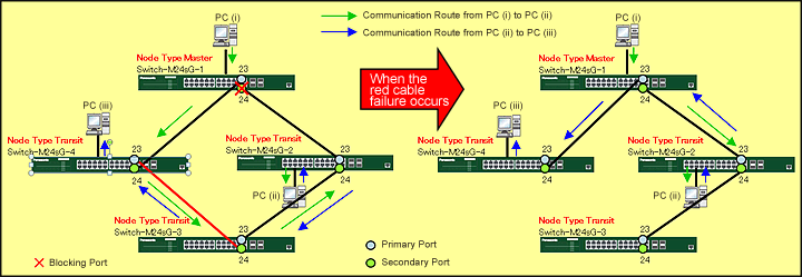
Overall setting flow
- 1. Set Switch-M24sG-1-4.
- 1) Set each parameter of ring protocol.
Common to 4 switches: Domain name (RING), primary port (Port 23), secondary port (Port 24), VLAN ID for control (10), and VLAN ID for data (1)
Switch-M24sG-1 only: Node role (Master)
* The system requires 1 master switch.
Switch-M24sG-2-4: Node role (Transit)
- 1) Set each parameter of ring protocol.
- 2. Connect Switch-M24sG and the terminal as shown in the configuration diagram.
* The primary and secondary ports must be connected in pairs between Switch-M24sGs. - 3. Confirm that communication between PCs is working and such communication can continue even when a twisted-pair cable between Switch-M24sGs is disconnected.
Setting Procedure
Step 1.
Connect the PC and Ethernet Switch using a twisted pair cable and console cable, and display the setting screen on Hyper terminal.
(Refer to Setting Example "Ethernet Switch Connection Procedure to a Console Port" for the procedure to display the setting screen on the console port)
Step 2.
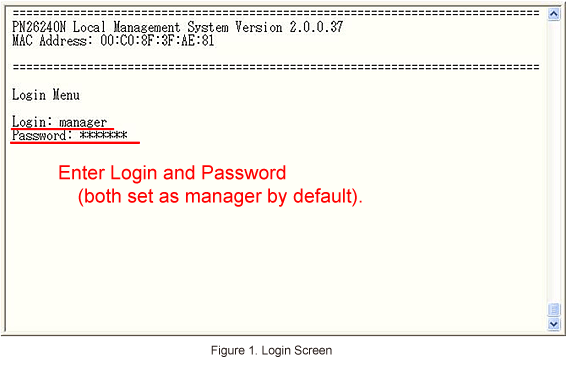
On the login screen, enter Login and Password (both set as manager by default), and login to the setting screen. (Refer to Figure 1)
Step 3.
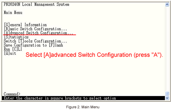
In Main Menu, select [A]dvanced Switch Configuration. (Refer to Figure 2)
Step 4.
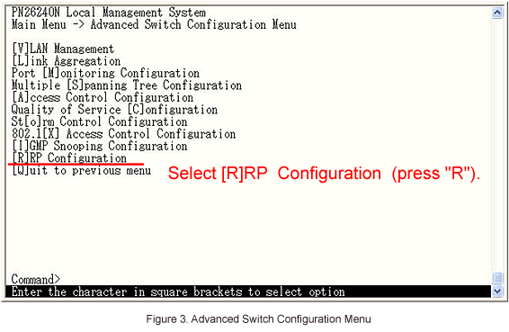
In Advanced Switch Configuration Menu, select [R]RP Configuration. (Refer to Figure 3)
Step 5.
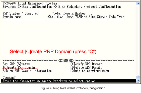
In Ring Redundant Protocol Configuration, select [C]reate RRP Domain to set ring protocol. (Refer to Figure 4)
Step 6.
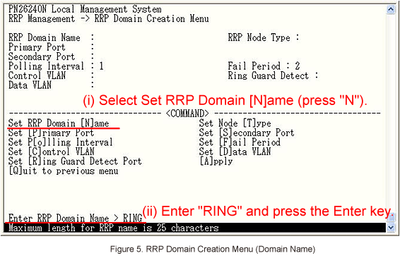
In RRP Domain Creation Menu, select Set RRP Domain [N]ame to enter the domain name (RING). (Refer to Figure 5)
Step 7.
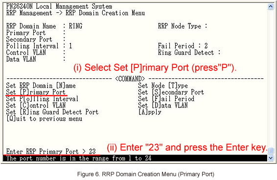
Then, select Set [P]rimary Port to set the primary port (Port 23). (Refer to Figure 6)
Step 8.
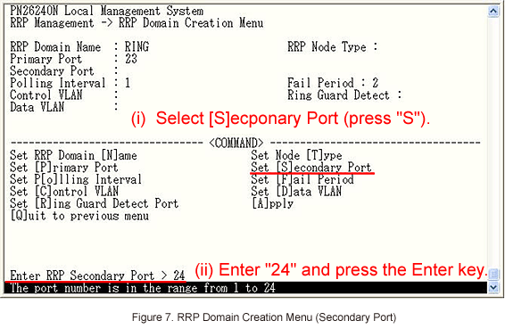
Then, select Set [S]econdary Port to set the secondary port (Port 24). (Refer to Figure 7)
Step 9.
Then, select Set [C]ontrol VLAN to set the control VLAN (VLAN ID 10). (Refer to Figure 8)
* For control VLAN, specify a VLAN ID which does not exist.

Step 10.
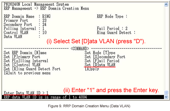
Then, select Set [D]ata VLAN to set the data VLAN (VLAN ID 1). (Refer to Figure 9)
* For the data VLAN, specify the VLAN ID which exists.
Step 11.
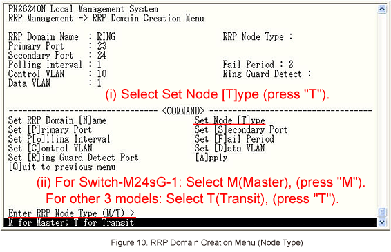
Then, select Set Node [T]ype to set node roles (Master for Switch-M24sG-1 and Transit for the remaining 3 switches). (Refer to Figure 10)
Step 12.
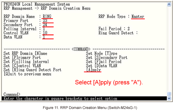
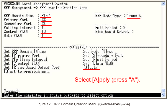
After performing all the settings, confirm that the settings are in the following status. Then, select [A]pply to apply the settings. (Refer to Figures 11 and 12)
Step 13.
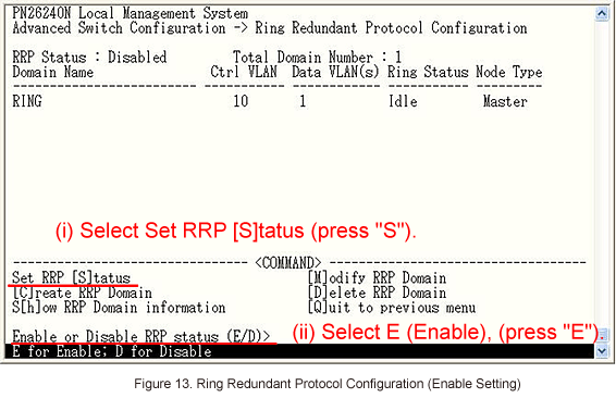
In Ring Redundant Protocol Configuration, select Set RRP [S]tatus to enable ring protocol. (Refer to Figure 13)
Step 14.
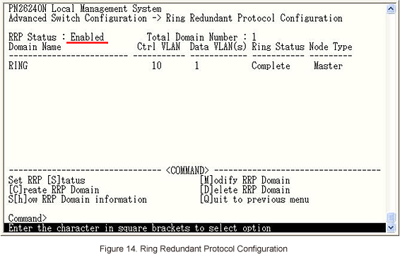
After performing the settings, confirm that the settings are in the following status. (Refer to Figure 14)
Step 15.
After completing the settings, save the settings using Save Configuration to [F]lash.
Step 16.
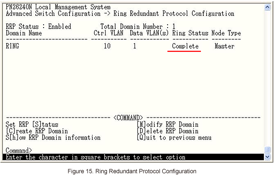
Referring to the configuration diagram, connect Switch-M24sG-1-4 and the PCs.
Then, confirm that Ring Status is changed to Complete. (Refer to Figure 15)
ここからサブメニューです。