ページの先頭です。
ここから本文です。
QoS Setting Procedure
Introduction
This setting example explains the procedure of QoS setting for switches.
Applicable models
| Applicable models | Applicable models Scheduling method | ||
|---|---|---|---|
| Product name | Product number | ||
| Switch-M48eG | PN28480K | ||
| Switch-M24eG | PN28240K | ||
| Switch-M16eG | PN28160K | ||
| Switch-M8eG | PN28080K | ||
| Switch-M24eGLPWR+ | PN28248 | ||
| Switch-M16eGLPWR+ | PN28168 | ||
| Switch-M12eGLPWR+ | PN28128 | ||
| Switch-M8eGLPWR+ | PN28088 | ||
| Switch-M5eGLPWR+ | PN28058 | ||
| Switch-M24PWR | PN23249K | ||
| Switch-M16PWR | PN23169K | ||
| Switch-M12PWR | PN23129K | ||
Overview
Perform packet priority control by QoS on switch.
When it receives a packet with DSCP 46, it prevents the voice or other delays at a time of congestion by giving CoS 5 to VLAN tag of the packet to increase priority.
This setting example explains describes a method to raise the priority of the packet with DSCP 46 by adding CoS 5 by using ACL.
For models without ACL, refer to the following instructions for settings.
<Switch-M12G (PN26120) and Switch-M12X (PN23120K)>
- By using Diffserv function, add CoS 5 to the packet with DSCP 46 .
<Switch-M12ePWR (PN271299), Switch-M8ePWR (PN27089K), Switch-M8esPWR (PN27089N) and Switch-S12PWR (PN22129K)>
- Using Diffserv function allows the priority control based on the DSCP value.
Raise the priority of the packet with DSCP 46.
Configuration Example

Overall setting flow
- 1. Create VLAN group 10 with ports 1-12 and 25-26 as its members.
- 2. Create VLAN group 20 with ports 13-26 as its members.
- 3. Perform setting to mark CoS 5 by ACL when a packet with DSCP 46 is received.
- 4. Enable QoS.
- 5. Confirm that no delay for the voice of IP Phone or no other troubles will occur even when a large amount of data is being sent/received between the PCs.
Setting Procedure
Step 1.
Connect the PC and Ethernet switch using a twisted pair cable and console cable, and display the setting screen on Hyper terminal.
(Refer to Setting Example "Ethernet Switch Connection Procedure to a Console Port" for the procedure to display the setting screen on the console port)
Step 2.
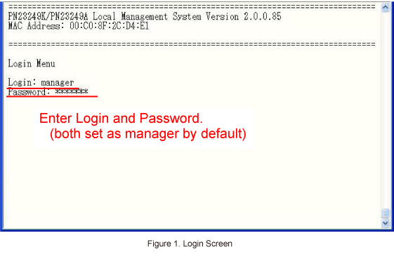
On the login screen, enter Login and Password (both set as manager by default), and login to the setting screen. (Refer to Figure 1)
Step 3.
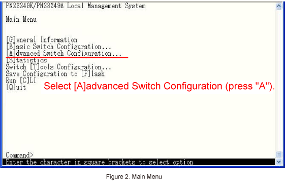
In Main Menu, select [A]dvanced Switch Configuration. (Refer to Figure 2)
Step 4.
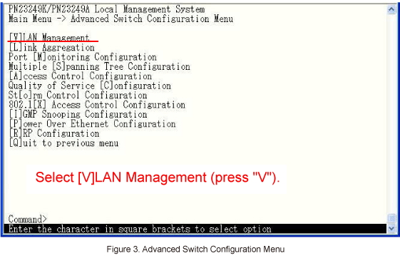
In Advanced Switch Configuration Menu, select [V]LAN Management. (Refer to Figure 3)
Step 5.
In VLAN Management Menu, create VLAN group 10 (with ports 1 to 12 and 25 to 26) and VLAN group 20 (with ports 13 to 26).
* For VLAN setting method, refer to the PoE series setting example "Ethernet switch VLAN Setting Procedure".
Step 6.
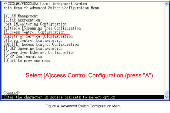
In Advanced Switch Configuration Menu, select [A]ccess Control Configuration. (Refer to Figure 4)
Step 7.
In Access Control Configuration Menu, set the access control.
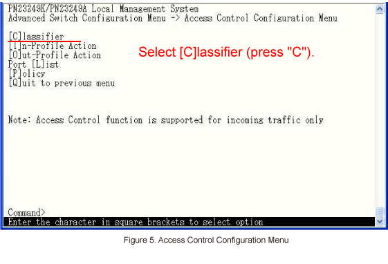
Select [C]lassifier, and set conditions for marking packets. (Refer to Figure 5)
Step 8.
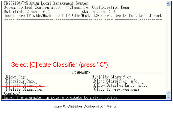
In Classifier Configuration Menu, select [C]reate Classifier. (Refer to Figure 6)
Step 9.
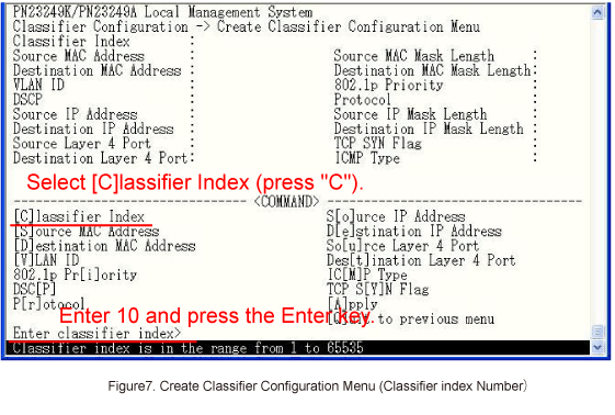
In Classifier Configuration Menu, select [C]lassifier Index and enter the index number.
(e.g. index number 10) (Refer to Figure 7)
Step 10.
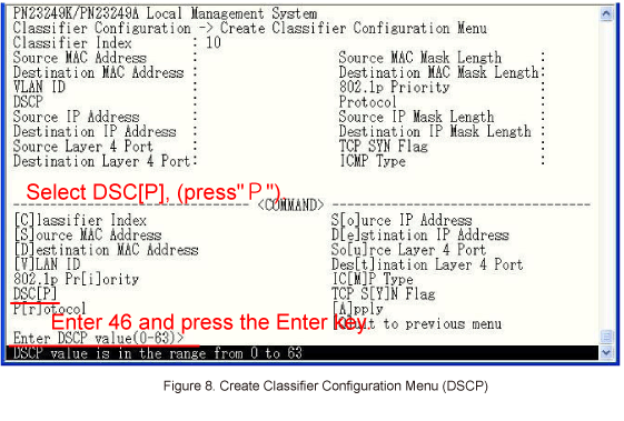
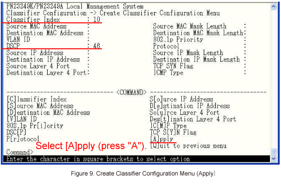
In Create Classifier Configuration Menu, select DSC[P] and set 46 as the DSCP value. (Refer to Figure 8)
Step 11.
In Create Classifier Configuration Menu, select [A]pply to apply the settings. (Refer to Figure 9)
Step 12.
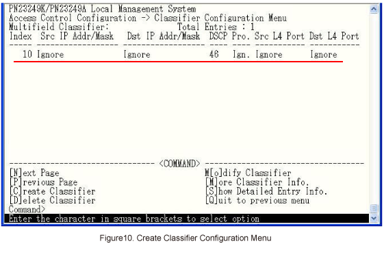
After performing the settings, confirm that the settings are in the following status. (Refer to Figure 10)
Step 13.
In Classifier Configuration Menu, select [Q]uit to previous menu to go back to Access Control Configuration Menu.
Step 14.
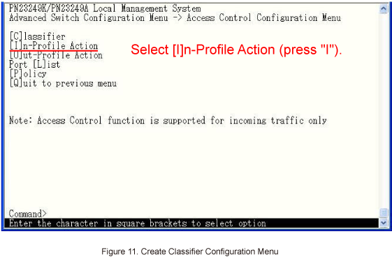
In Access Control Configuration Menu, select [I]n-Profile Action and set the CoS value to mark. (Refer to Figure 11)
Step 15.
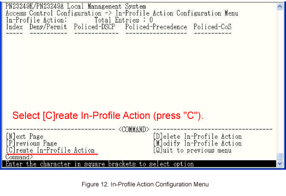
In In-Profile Action Configuration Menu, select [C]reate In-Profile Action. (Refer to Figure 12)
Step 16.
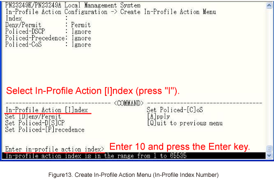
In Create In-Profile Action Menu, select In-Profile Action [I]ndex and set 10 as the index number. (Refer to Figure 13)
Step 17.
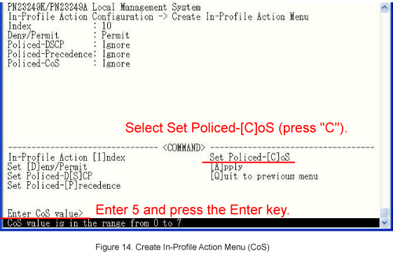
In Create In-Profile Action Menu, select Set Policed-[C]oS and set the CoS value of 5. (Refer to Figure 14)
Step 18.
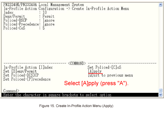
In Create In-Profile Action Menu, select [A]pply to apply the settings. (Refer to Figure 15)
Step 19.
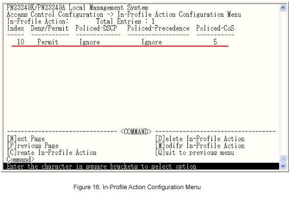
After performing the settings, confirm that the settings are in the following status. (Refer to Figure 16)
Step 20.
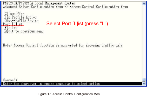
In Access Control Configuration Menu, select Port [L]ist and configure ports on which target packets are received. (Refer to Figure 17)
Step 21.
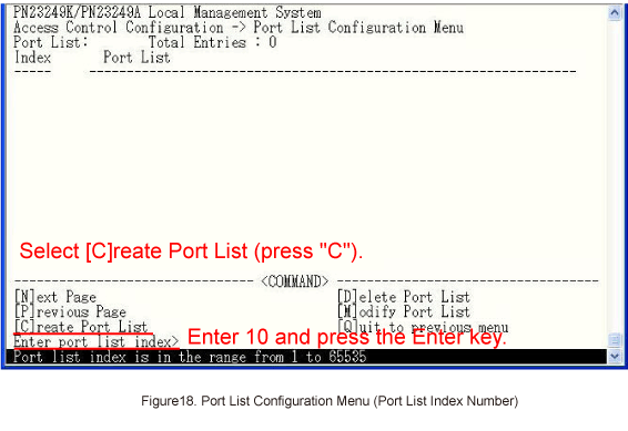
In Port List Configuration Menu, select [C]reate Port List and set 10 as the index number. (Refer to Figure 18)
Step 22.
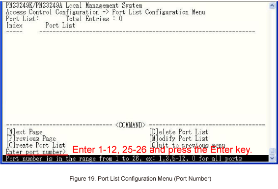
Go on to set ports 1 to 12 and 25 to 26. (Refer to Figure 19)
Step 23.
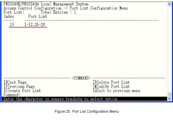
After performing the settings, confirm that the settings are in the following status. (Refer to Figure 20)
Step 24.
In Port List Configuration Menu, select [Q]uit to previous menu to go back to Access Control Configuration Menu.
Step 25.
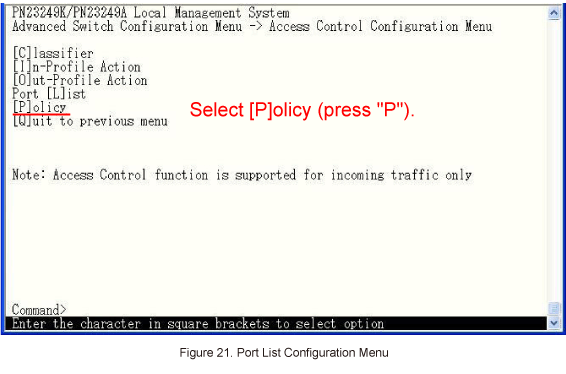
In Access Control Configuration Menu, select [P]olicy and associate the index numbers created at Classifier, In-Profile Action and Port [L]ist. (Refer to Figure 21)
Step 26.
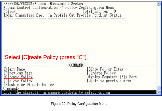
In Policy Configuration Menu, select [C]reate Policy. (Refer to Figure 22)
Step 27.
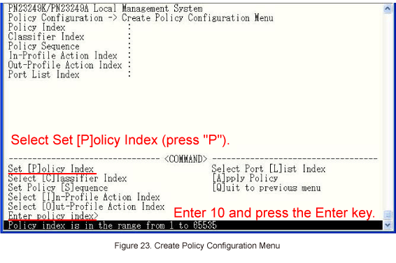
In Create Policy Configuration Menu, select Set [P]olicy Index and set index number 10. (Refer to Figure 23)
Step 28.
In Create Policy Configuration Menu, select Select [C]lassifier Index and set index number 10.
Step 29.
In Create Policy Configuration Menu, select Set Policy [S]equence and set sequence number 10.
* The sequence numbers indicate execution priority when multiple policies are created.
(The smaller value has higher the priority. *Except for M12GL3, for which the larger value has higher priority)
Step 30.
In Create Policy Configuration Menu, select Select [I]n-Profile Action Index and set index number 10.
Step 31.
In Create Policy Configuration Menu, select Select Port [L]ist Index and set index number 10.
Step 32.
In Create Policy Configuration Menu, select [A]pply to apply the settings.
Step 33.
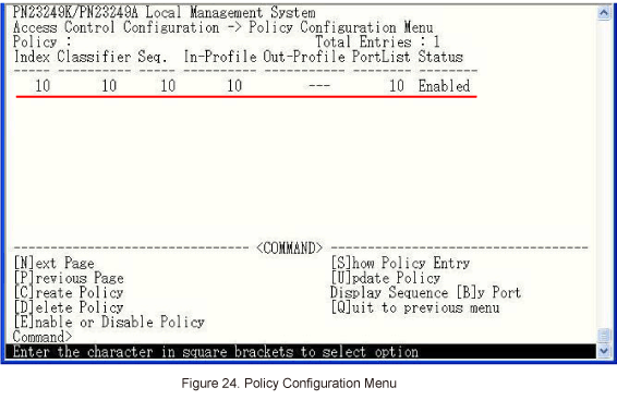
When configured, confirm that the settings are in the following status. (Refer to Figure 24)
Step 34.
In Policy Configuration Menu, select [Q]uit to previous menu to go back to Access Control Configuration Menu.
Step 35.
In Access Control Configuration Menu, select [Q]uit to previous menu to go back to Advanced Switch Configuration Menu.
Step 36.
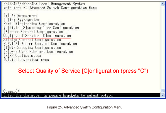
In Advanced Switch Configuration Menu, select Quality of Service [C]onfiguration. (Refer to Figure 25)
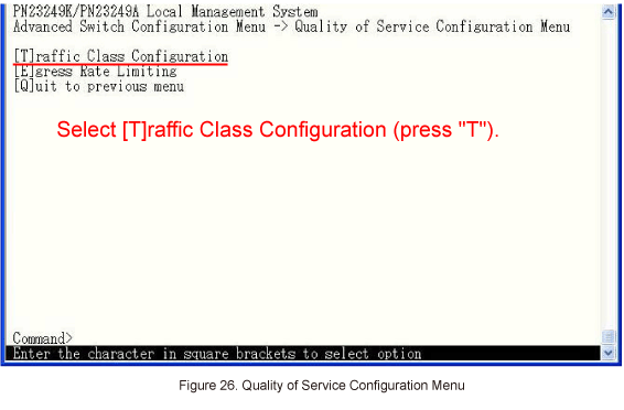
Step 37.
In Quality of Service Configuration Menu, select [T]raffic Class Configuration. (Refer to Figure 26)
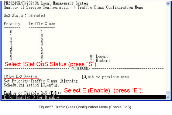
Step 38.
In Traffic Class Configuration Menu, select [S]et QoS Status and enable QoS. (Refer to Figure 27)
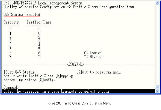
Step 39.
After performing the settings, confirm that the settings are in the following status. (Refer to Figure 28)
Step 40.
After completing the settings, save the settings using Save Configuration to [F]lash.
Step 41.
Confirm that no delay for the voice of IP Phone or no other troubles will occur even when a large amount of data is being sent/received between the PCs.
ここからサブメニューです。