ページの先頭です。
ここから本文です。
Ethernet Switch VLAN Setting Procedure
Introduction
This section explains the procedure of the Ethernet Switch VLAN setting.
Applicable models
Overview
Ports are divided into 1-12 and 13-25 VLAN groups to allow communication among ports in the same group through uplink.
Ports 1-25 are set to PC and port 26 is set to the uplink port.

Setting description and procedure(Common to both Switch-M24PWR-1 and Switch-M24PWR-2)
- Set ports 1-12 and 26 to VLAN Group 10 (VLAN ID=10, VLAN name=Group 10)
- Set ports 13-26 to VLAN Group 20 (VLAN ID=20, VLAN name=Group 20)
- Ports 1-25 send and receive as untagged ports, and port 26 send and receive as a tagged port.
Overall setting flow
- 1.Make the Switch-M24PWR-1 VLAN setting.
- 1) From the “VLAN Creation Menu”, set the VLAN ID, VLAN Name, and Port Members.
- 2) From the “VLAN Port Configuration Menu”, set the PVID and configure the Untag VLAN.
- 3) Save the settings.
- 2.Make the Switch-M24PWR-2 VLAN setting.
- 1) From the “VLAN Creation Menu”, set the VLAN ID, VLAN Name, and Port Members.
- 2) From the “VLAN Port Configuration Menu”, set the PVID and configure the Untag VLAN.
- 3) Save the settings.
- 3.Connect Switch-M24PWR-1 and Switch-M24PWR-2 and confirm that communication among the same VLAN is possible.
Setting Procedure
Step 1.
Use a twisted pair cable and a console cable to connect the PC and Ethernet Switch, and display the setting screen on the Hyper Terminal.
(For the setting screen display method on the console port, refer to the setting example “Method for Connecting to the Ethernet Switch Console Port.”)
Step 2.
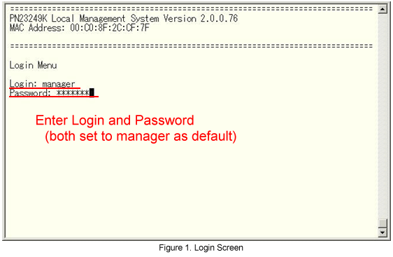
On the login screen, enter in Login and Password (both are manager in the initial state) to log into the setting screen.
(See Fig.1.)
Step 3.
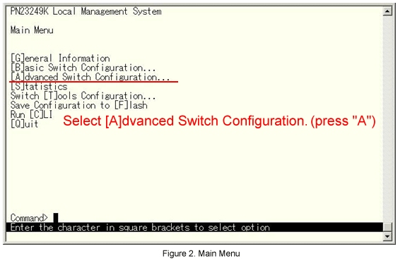
From the Main Menu, select Advanced Switch Configuration. (See Fig.2.)
Step 4.
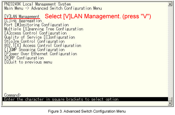
From the Advanced Switch Configuration menu, select [V]LAN Management. (See Fig.3.)
Step 5.
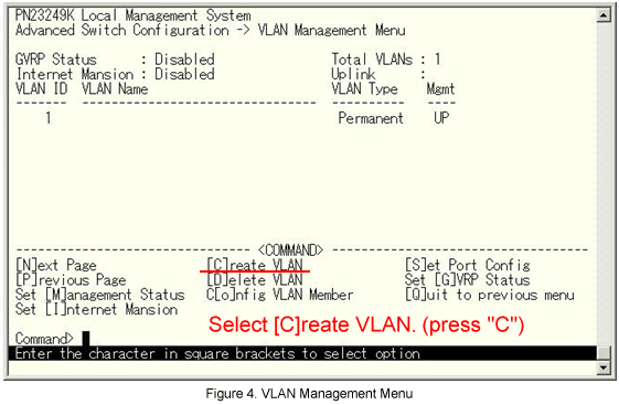
From the VLAN Management menu, select Create VLAN. (See Fig.4.)
Step 6.
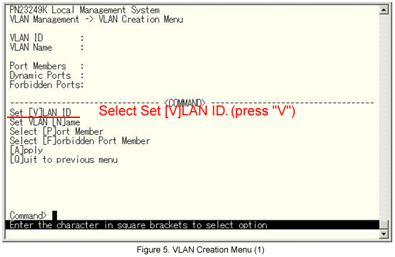
From the VLAN Creation Menu, select Set [V]LAN ID. (See Fig.5.)
Step 7.
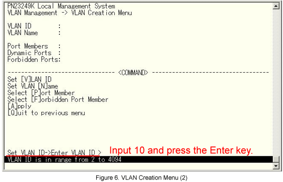
The message shown in Fig.6 is displayed. Enter the VLAN ID.
Step 8.
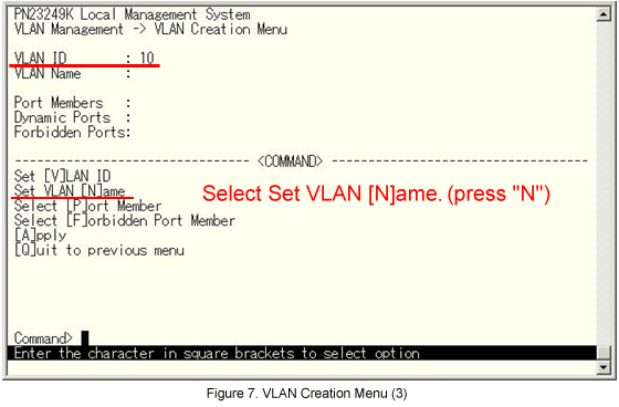
10 is entered in VLAN ID. Next, from the screen shown in Fig.7 select Set VLAN [N]ame.
Step 9.
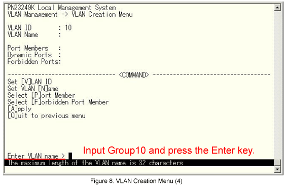
The message shown in Fig.8 is displayed. Enter the VLAN name.
Step 10.
Group10 is entered in VLAN Name. Next, from the screen shown in Fig.9, select the Select [P]ort Member.
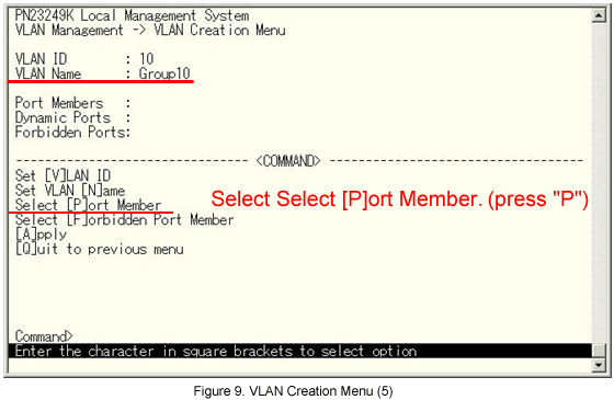
Step 11.
The message shown in Fig.10 is displayed. Select the port that will be a member.
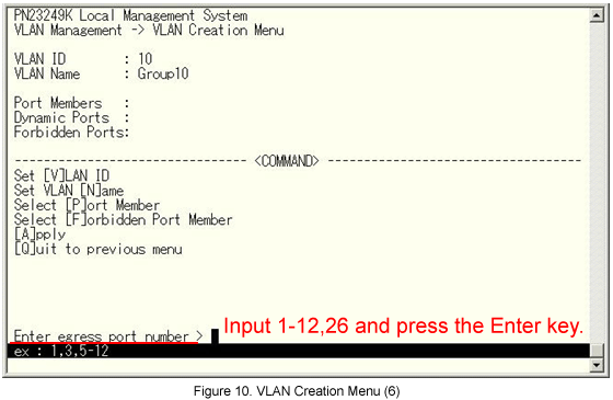
Step 12.
1-12,26 are entered in Port Members. Finally, select [A]pply to complete the VLAN configuration.
*If Quit to previous menu is selected without executing Apply, the display returns to the previous screen without setting anything.
Step 13.
Repeat Steps 5-12 to create VLAN20 in the same manner as VLAN10.
(VLAN ID=20, VLAN name= Group 20, Port Member=13-26)
Step 14.
From the screen shown in Fig.11, select Set [P]ort Config .
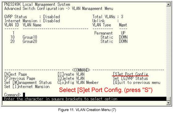
Step 15.
From the VLAN Port Configuration menu, select Set Port [V]ID. (See Fig.12.)
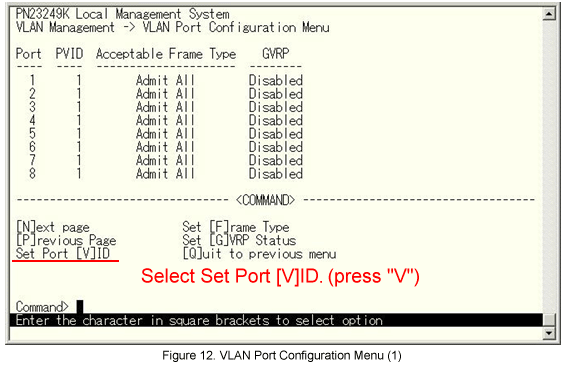
Step 16.
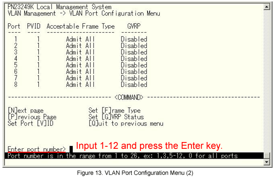
The message is displayed. Select the port member for which the Port VLAN ID will be changed. (See Fig.13.)
Step 17.
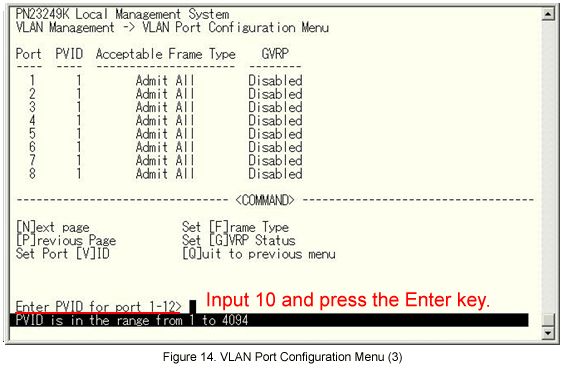
The message shown in Fig.14 is displayed. Enter the PVID.
Step 18.
Repeat steps 15-17 to set the PVID for ports 13-25 to 20.
Step 19.
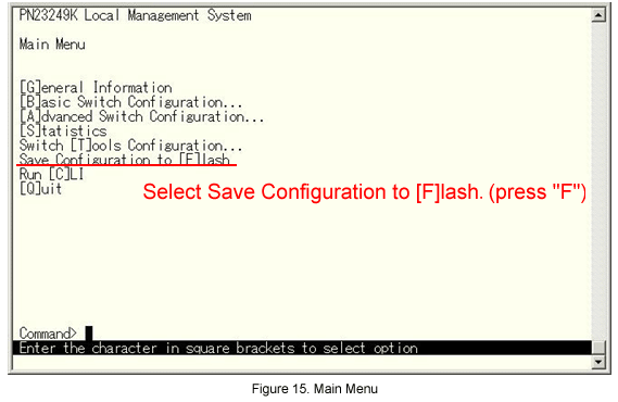
Return to the Main Menu and select Save Configuration to [F]lash. (See Fig.15.)
Step 20.
Select Save Configuration to [F]lash. (Press “F”.)
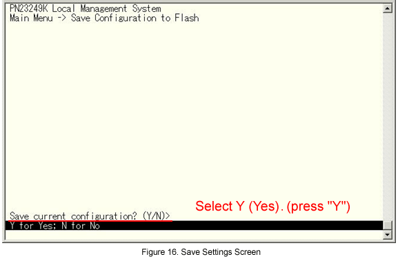
The setting is now completed. Connect the device and check the communication.
ここからサブメニューです。