ページの先頭です。
ここから本文です。
IGMP Snooping Setting Procedure
Introduction
This setting example explains the procedure of the IGMP Snooping setting for switches.
Applicable models
| Applicable models | |
|---|---|
| Product name | Product number |
| Switch-M24eGLPWR+ | PN28248 |
| Switch-M16eGLPWR+ | PN28168 |
| Switch-M12eGLPWR+ | PN28128 |
| Switch-M8eGLPWR+ | PN28088 |
| Switch-M5eGLPWR+ | PN28058 |
| Switch-M24PWR | PN23249K |
| Switch-M16PWR | PN23169K |
| Switch-M12PWR | PN23129K |
| Switch-M8ePWR | PN27089K |
| Switch-M8esPWR | PN27089N |
Overview
Set switches so that IGMP Snooping is used, and from multicast transmission terminals, multicast is only transferred to terminals requesting multicast.
Configuration Example

Overall setting flow
- 1.Set Switch-M24X.
- 1) Set 192.168.1.253/24 as the IP address.
- 2) Enable IGMP Snooping.
- 3) Enable multicast filtering.
- 4) Add the IGMP packet to the router port detection method.
- 2.Connect the multicast transmission terminal to the L3 Ethernet switch, and connect the multicast requesting and non-requesting terminals to Switch-M24X.
- 3.When a multicast requesting terminal requests multicast, confirm that packets are only transmitted to requesting terminals and not to non-requesting terminals.
Setting Procedure
Step 1.
Connect the PC and Ethernet switch using a twisted pair cable and console cable, and display the setting screen on the Hyper terminal.
(Refer to Setting Example "Ethernet switch Connection Procedure to a Console Port" for the procedure to display the setting screen on the console port)
Step 2.
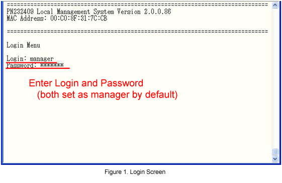
On the login screen, enter Login and PassWord (both set as "manager" by default), and login to the setting screen.
(Refer to Figure 1)
Step 3.
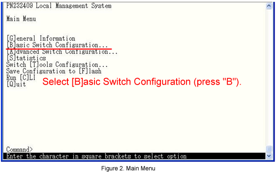
In Main Menu, select [B]asic Switch Configuration. (Refer to Figure 2)
Step 4.
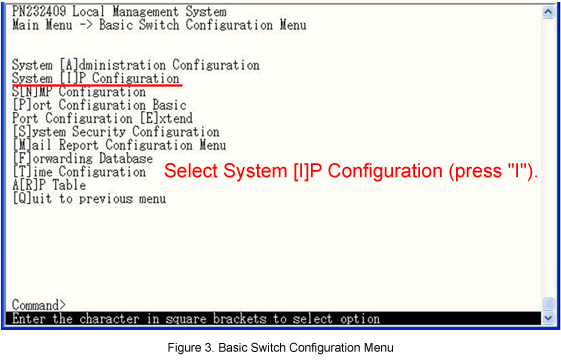
In Basic Switch Configuration, select System [I]P Configuration. (Refer to Figure 3)
Step 5.
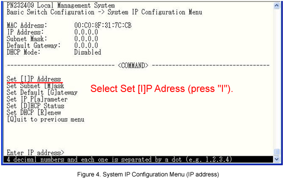
In System IP Configuration Menu, select Set [I]P Address and set the IP address (192.168.1.253). (Refer to Figure 4)
Step 6.
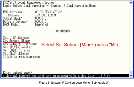
In System IP Configuration Menu, select Set Subnet [M]ask and set the subnet mask (255.255.255.0). (Refer to Figure 5)
Step 7.
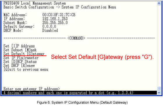
In System IP Configuration Menu, select Set Default [G]ateway and set the default gateway (192.168.1.254). (Refer to Figure 6)
Step 8.
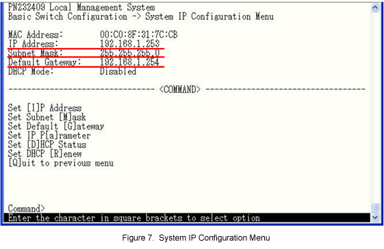
After performing all the settings, confirm that the settings are in the following status. (Refer to Figure 7)
Step 9.
In System IP Configuration Menu, select [Q]uit to previous menu and go back to Basic Switch Configuration Menu.
Step 10.
In Basic Switch Configuration Menu, select [Q]uit to previous menu and go back to Main Menu.
Step 11.
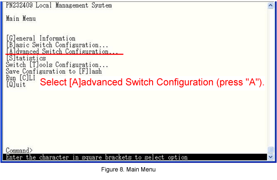
In Main Menu, select [A]dvanced Switch Configuration. (Refer to Figure 8)
Step 12.
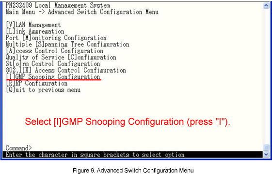
In Advanced Switch Configuration Menu, select [I]GMP Snooping Configuration. (Refer to Figure 9)
Step 13.
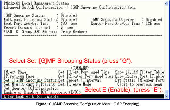
In IGMP Snooping Configuration Menu, select Set I[G]MP Snooping Status to enable the IGMP Snooping. (Refer to Figure 10)
Step 14.
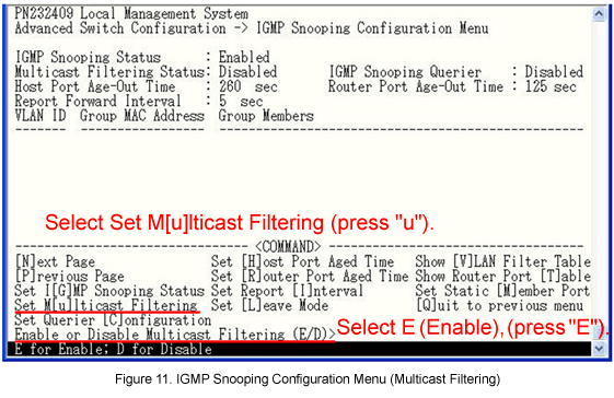
In IGMP Snooping Configuration Menu, select Set M[u]lticast Filtering and enable the multicast filtering.
* Set this if the multicast transmission terminal is under Switch-M24X, and the packets from the multicast group not being studied on the IGMP Snooping management table should not be transferred to other ports.
However, regardless of the study status, the packets are always transferred to the router port.
Step 15.
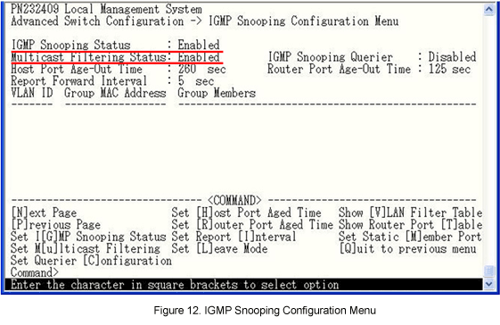
After performing all the settings, confirm that the settings are in the following status. (Refer to Figure 12)
Step 16.
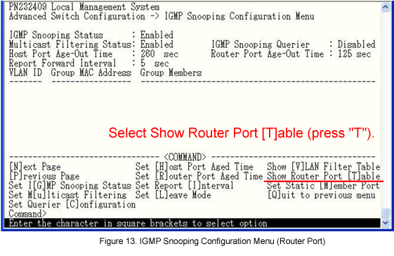
In IGMP Snooping Configuration Menu, select Show Router Port [T]able. (Refer to Figure 13)
Step 17.
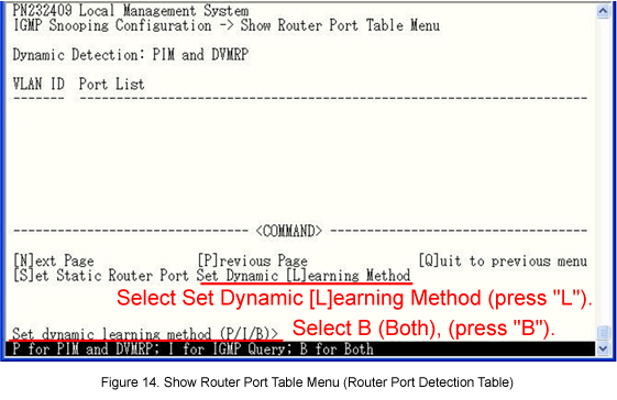
In Show Router Port Table Menu, select Set Dynamic [L]earning Method and add the IGMP packet as the router port detection method. (Refer to Figure 14)
Step 18.
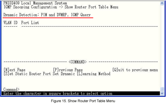
After performing the settings, confirm that the settings are in the following status. (Refer to Figure 15)
Step 19.
After completing the settings, save the settings using Save Configuration to [F]lash.
Step 20.
Confirm that multicast requesting terminals can receive multicasts, while non-requesting terminals cannot.
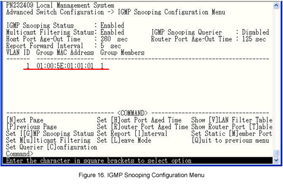
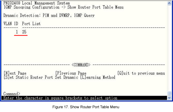
Confirm that the connection port to the L3 Ethernet switch (the port receiving the IGMP Query) is studied on the router port (refer to Figure 16),
and that the connection port of the multicast requesting terminal is studied on the IGMP Snooping group table. (Refer to Figure 17)
ここからサブメニューです。