ページの先頭です。
ここから本文です。
Ethernet Switch Spanning Tree Setting Procedure
Introduction
This section explains the procedure of the Ethernet Switch spanning tree setting.
Applicable models
| Applicable models | |
|---|---|
| Product name | Product number |
| Switch-M24eGLPWR+ | PN28248 |
| Switch-M16eGLPWR+ | PN28168 |
| Switch-M12eGLPWR+ | PN28128 |
| Switch-M8eGLPWR+ | PN28088 |
| Switch-M5eGLPWR+ | PN28058 |
| Switch-M24PWR | PN23249K |
| Switch-M16PWR | PN23169K |
| Switch-M12PWR | PN23129K |
| Switch-M8ePWR | PN27089K |
| Switch-M8esPWR | PN27089N |
Overview
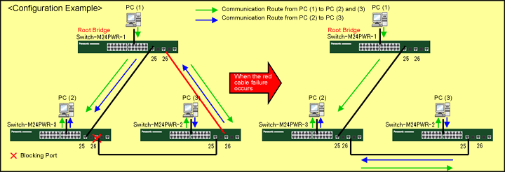
Activating the spanning tree (RSTP) blocks specific ports to prevent the occurrence of broadcast storms, etc. In addition,when a route failure occurs, the communication route can be automatically switched to continue communications.
Three switches are used. Ports 25 and 26 build loop configurations.
Setting description and procedure
?Enable spanning tree (RSTP).
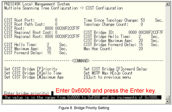
?Change the Priority to the smallest value (0x6000 in the example) so that Switch-M24PWR-1 becomes a root bridge.
?Change the Priority of Switch-M24PWR-2 to a smaller value (0x7000 in the example) than the Priority of Switch-M24PWR-3 (0x8000 at default setting) so that the Switch-M24PWR-3 port (connection port to Switch-M24PWR-2) becomes a blocking port.
Overall setting flow
- 1. From the “Multiple Spanning Tree Configuration Menu” of Switch-M24PWR-1, enable Global MSTP.
- 2. From the “CIST Configuration Menu” of Switch-M24PWR-1, set the CIST Bridge Priority to 0x6000.
- 3. Save the settings.
- 4. From the “Multiple Spanning Tree Configuration Menu” of Switch-M24PWR-2, enable Global MSTP.
- 5. From the “CIST Configuration Menu” of Switch-M24PWR-2, set the CIST Bridge Priority to 0x7000
- 6. Save the settings.
- 7. From the “Multiple Spanning Tree Configuration Menu” of Switch-M24PWR-3, enable Global MSTP.
- 8. From the “CIST Configuration Menu” of Switch-M24PWR-3, set the CIST Bridge Priority to 0x8000.
- 9. Save the settings.
- 10. Connect Switch-M24PWR-1, Switch-M24PWR-2, and Switch-M24PWR-3 and check the communication.
Method of login and access to the spanning tree setting screen (Common to Switch-M24PWR-1, Switch-M24PWR-2, and Switch-M24PWR-3)
Step 1.
Use a twisted pair cable and a console cable to connect the PC and Ethernet Switch, and display the setting screen on the Hyper Terminal.
(For the setting screen display method on the console port, refer to the setting example “Method for Connecting to the Ethernet Switch Console Port.”)
Step 2.
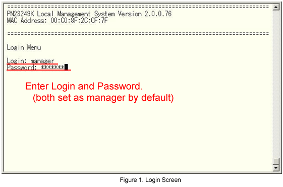
On the login screen, enter in Login and Password (both are manager in the initial state) to log into the setting screen.
(See Fig.1.)
Step 3.
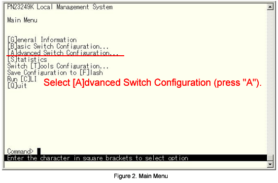
From the Main Menu, select Advanced Switch Configuration. (See Fig.2.)
Step 4.
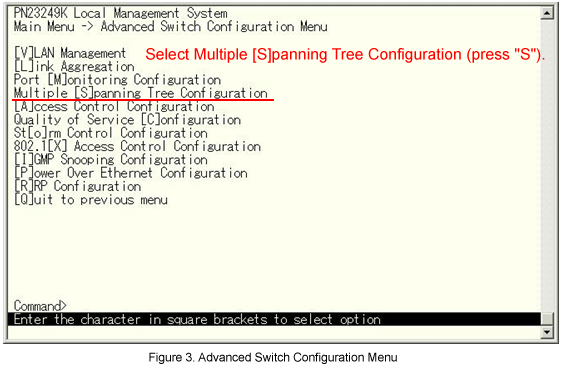
From the Advanced Switch Configuration menu, select Multiple [S]panning Tree Configuration. (See Fig.3.)
Step 5.
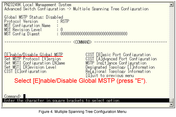
From the Multiple Spanning Tree Configuration menu, select [E]nable/Disable Global MSTP. (See Fig.4.)
Step 6.
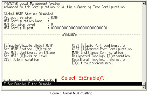
The message shown in Fig.5 is displayed. Select E (Enable).
Step 7.
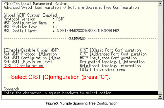
Next, from Fig.6 select CIST [C]onfiguration.
Switch-M24PWR-1 setting
Step 8.
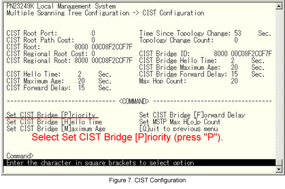
From the CIST Configuration menu, select Set CIST Bridge [P]riority. (See Fig.7.).
Step 9.
The message shown in Fig.8 is displayed. Enter the Priority value.
Step 10.
Repeat steps 7-9 to set the Priority value for Switch-M24PWR-2 and Switch-M24PWR-3 the same way as for Switch-M24PWR-1.
(Set 0x7000 for Switch-M24PWR-2, and leave the default value (0x8000) for Switch-M24PWR-3.)
Step 11.
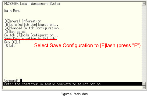
Return to the Main Menu and select Save Configuration to [F]lash. (See Fig.9.)
Step 12.
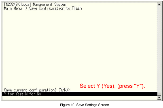
The message shown in Fig.10 is displayed. Select Y(Yes) to save the setting.
Step 13.
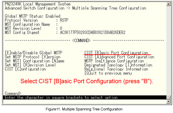
When completed the settings, connect each device and from the screen shown in Fig.11 select CIST [B]asic Port Configuration.
Step 14.
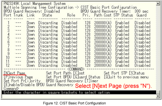
From the CIST Basic Port Configuration menu, select [N]ext Page to display Port 25 and Port 26. (See Fig.12.)
Step 15.
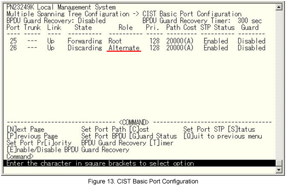
From the screen shown in Fig.13, check the state of Ports 25 and 26 for each Switch-M24PWR.
Confirm that Port 26 of Switch-M24PWR-3 is blocked (Alternate).
The setting is now completed.
Checking the spanning tree operation
1) Conduct continuous Ping communication between PC (1) and PC (2).
?PC (1) IP address: 192.168.1.10/24, PC (2) IP address: 192.168.1.20/24
?At the command prompt continuously enter Ping.
?Execute a Ping from PC (1) to PC (2).
?Execute a Ping from PC (2) to PC (1).

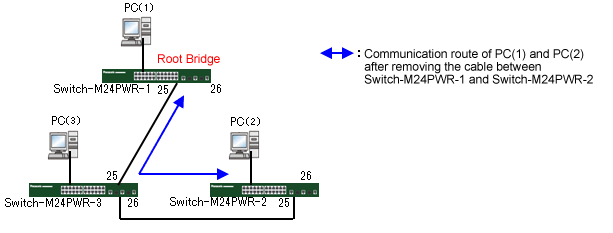
2) Remove the cable from between Switch-M24PWR-1 and Switch-M24PWR-2.
?Confirm that the Ping times out for a few seconds and then communication resumes.
?Confirm that the Switch-M24PWR-3 blocking port opens and the communication route between PC (1) and PC (2) is switched.
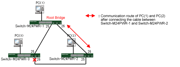
3) Reconnect the cable between Switch-M24PWR-1 and Switch-M24PWR-2.
?Confirm that the Ping times out for a few seconds and then communication resumes.
?Confirm that the Switch-M24PWR-3’s port 26 is changed to the blocking port and the communication route between PC (1) and PC (2) is switched.
ここからサブメニューです。