ページの先頭です。
ここから本文です。
Ethernet Switch Link Aggregation Setting Procedure
Introduction
This section explains the procedure of the Ethernet Switch Link Aggregation setting.
Applicable models
Overview
The giga ports are bundled using link aggregation to connect between switches and expand the communication bandwidth (to a maximum of 2Gbps in this setting).

Setting description and procedure
?The Switch-M24PWR-1 Link Aggregation is LACP (Port=25-26 Mode=Active).
?The Switch-M24PWR-2 Link Aggregation is LACP (Port=25-26 Mode=Passive).
*When setting the LACP Link Aggregation, use the combination Active-Active or Active-Passive for the Ethernet Switch mode (it will not function if the both are set to Passive).
*All of the ports bundled as a Link Aggregation must exist within the same VLAN.
Overall setting flow
- 1. From the Link Aggregation (Trunk Configuration) Menu of Switch-M24PWR-1, set the Group ID, Port Member, and Mode.
- 2. Save the settings.
- 3. From the Link Aggregation (Trunk Configuration) Menu of Switch-M24PWR-2, set the Group ID, Port Member, and Mode.
- 4. Save the settings.
- 5. Connect Switch-M24PWR-1 and Switch-M24PWR-2 and confirm that they can communicate.
(Make sure ports 25 and 26 of both switches do not form a loop.)
Method of login and access to the Link Aggregation setting screen (Common to both Switch-M24PWR-1 and Switch-M24PWR-2)
Step 1.
Use a twisted pair cable and a console cable to connect the PC and Ethernet Switch, and display the setting screen on the Hyper Terminal.
(For the setting screen display method on the console port, refer to the setting example “Method for Connecting to the Ethernet Switch Console Port.”)
Step 2.
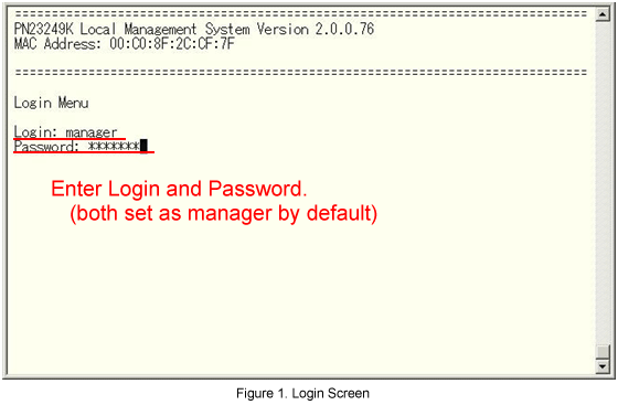
On the login screen, enter in Login and Password (both are manager in the initial state) to log into the setting screen.
(See Fig.1.)
Step 3.
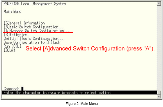
From the Main Menu, select Advanced Switch Configuration. (See Fig.2.)
Step 4.
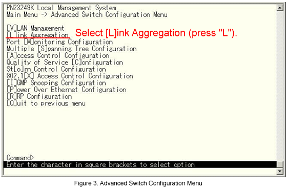
From the Advanced Switch Configuration menu, select [L]ink Aggregation. (See Fig.3.)
Switch-M24PWR-1 setting
Step 5.
From the Advanced Switch Configuration menu, select [L]ink Aggregation. (See Fig.3.)

Step 6.
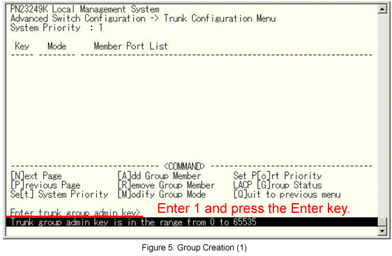
The message shown in Fig.5 is displayed. Enter the Group ID.
Step 7.
The message in Fig.6 is displayed. Enter the port No. that will be a member.

Step 8.
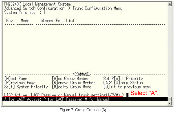
The message shown in Fig.7 is displayed. Select A (Active).
Step 9.
When the Switch-M24PWR-1 setting is completed, return to the Main Menu and select Save Configuration to [F]lash.
(See Fig.8.)

Step 10.
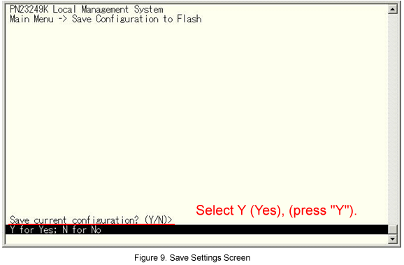
The message shown in Fig.9 is displayed. Select Y(Yes) to save the setting.
Step 11.
Proceed to the Switch-M24PWR-2 setting.
Proceed to the Switch-M24PWR-2 setting.
Step 12.
From the Link Aggregation (Trunk Configuration) menu, select [A]dd Group Member. (See Fig.10.)

Step 13.
The message shown in Fig.11 is displayed. Enter the Group ID.

Step 14.
The message shown in Fig.12 is displayed. Enter the port No. that will be a member.

Step 15.
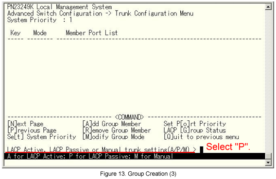
The message shown in Fig.13 is displayed. Select P (Passive).
Step 16.
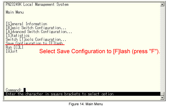
When the Switch-M24PWR-2 setting is completed, return to the Main Menu and select Save Configuration to [F]lash.
(See Fig.14.)
Step 17.
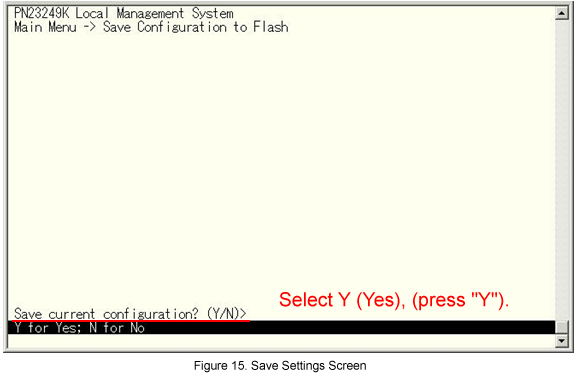
The message shown in Fig.15 is displayed. Select Y(Yes) to save the setting.
The setting is now completed. Connect the device and check the communication.
ここからサブメニューです。