ページの先頭です。
ここから本文です。
Syslog Transfer Setting Procedure (for WEB)
Introduction
This setting example explains the procedure of the Syslog transfer setting for switches for WEB.
Applicable models
| Applicable models | |
|---|---|
| Product number | Product name |
| PN28248 | Switch-M24eGLPWR+ |
| PN28168 | Switch-M16eGLPWR+ |
| PN28128 | Switch-M12eGLPWR+ |
| PN28088 | Switch-M8eGLPWR+ |
| PN28058 | Switch-M5eGLPWR+ |
| PN23249K | Switch-M24PWR |
| PN23169K | Switch-M16PWR |
| PN23129K | Switch-M12PWR |
Overview
Settings for transferring Syslog of the switch to another host are configured.
This setting enables the switch to transfer its system log to terminals including Syslog servers.
Configuration Example

Setting Flow
- 1. Connect to the Web management screen of Switch-M24PWR.
- 2. Set Switch-M24PWR.
- 1) Enable the function to transfer the logs to Syslog servers.
- 2) Register data of the Syslog server.
- 3. Connect the Syslog server to Switch-M24PWR.
- 4. Confirm that the link-up log is transferred to the Syslog server.
Setting Procedure
Step 1. Connect to the Web management screen of Switch-M24PWR and login.
Connect the PC and Ethernet Switch using a twisted pair cable, and connect to the Web management screen of Switch-M24PWR.
(Refer to setting example “Connection Procedures to Ethernet Switch Web Management Screen” for the procedure to connect to the Web management screen)

Step 2. Enable the function to transfer the logs to Syslog servers.
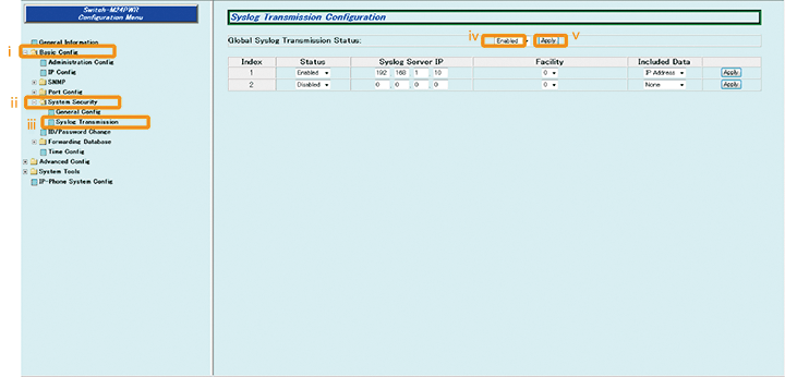
1) Select “Basic Config” → “System Security” → “Syslog Transmission” (i → ii → iii).
2) Change Global Syslog Transmission Status to “Enabled” (iv).
3) Apply the change by “Apply” (v).

Step 3. Set the IP address of the Syslog server and data to be included in the log message.
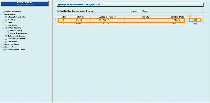
1) Change Status to “Enabled,” Syslog Server IP to “192.168.1.10,” and Included Data to “IP Address” (i).
2) Apply the change by “Apply” (ii).

Step 4. Save the settings.
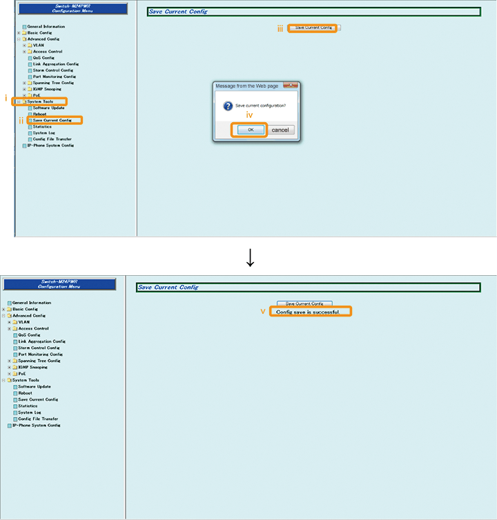
1) Select “System Tools” → ”Save Current Config”(i → ii).
2) Save the settings by “Save Current Config”(iii).
3) Execute saving by “OK”(iv).
4) Confirm that the settings are saved successfully (v).

Step 5. Connect the devices.
Referring to the configuration example on page 1, connect the devices.
Step 6. Execute operation check.
Confirm that the log is transferred to the Syslog server when the terminal is connected to an open port for link-up.
ここからサブメニューです。