ページの先頭です。
ここから本文です。
PoE Power Supply Switch On/Off Procedure (for WEB)
Introduction
This setting example explains the procedure of the PoE powering on/off setting for switches for WEB.
Applicable models
| Applicable models | |
|---|---|
| Product name | Product number |
| PN28248 | Switch-M24eGLPWR+ |
| PN28168 | Switch-M16eGLPWR+ |
| PN28128 | Switch-M12eGLPWR+ |
| PN28088 | Switch-M8eGLPWR+ |
| PN28058 | Switch-M5eGLPWR+ |
| PN23249K | Switch-M24PWR |
| PN23169K | Switch-M16PWR |
| PN23129K | Switch-M12PWR |
Overview
The settings of PoE powering on/off on Ethernet Switch are configured.
This setting enables to reboot the terminals such as PoE-compliant cameras by powering them on/off.
Configuration Example

Setting Flow
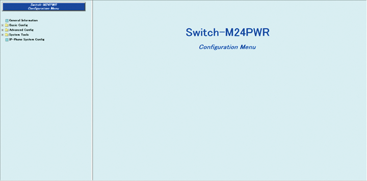
- 1. Connect to the Web management screen of Switch-M24PWR.
- 2. Turn off the PoE power supply function of Port 1.
- 3. Turn on the PoE power supply function of Port 1.
Setting Procedure
Step 1. Connect the PC and Ethernet Switch using a twisted pair cable, and connect to the Web management screen of Switch-M24PWR.
(Refer to setting example “Connection Procedures to Ethernet Switch Web Management Screen” for the procedure to connect to the Web management screen)
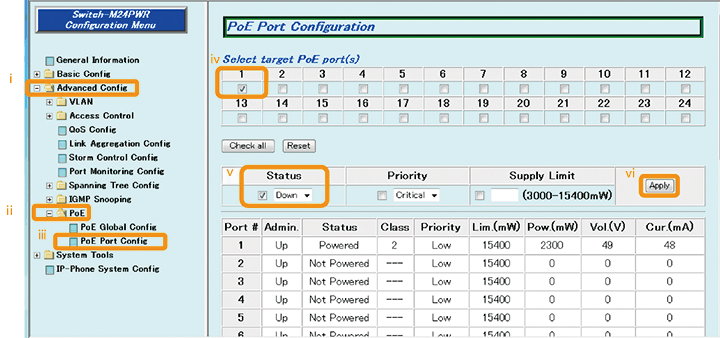
Step 2. Turn off the PoE power supply function of Port 1.
1) Select “Advanced Config” → “PoE” → “PoE Port Config” (i → ii → iii).
2) Place a check in “1” for Select target PoE port(s) (iv).
3) Select “Down” for Status and place a check (v).
4) Apply the change by “Apply” (vi).
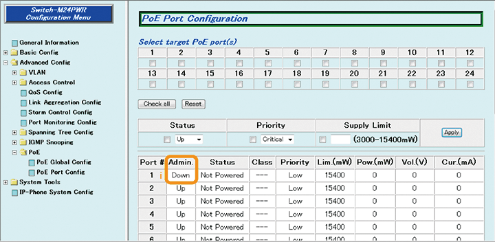
Step 3. Confirm that the PoE power supply function of Port 1 has been turned off (Down).
1) Confirm that Admin of Port 1 is “Down” (i).
* The power supply of the PoE-compliant terminal connected to Port 1 is turned off.
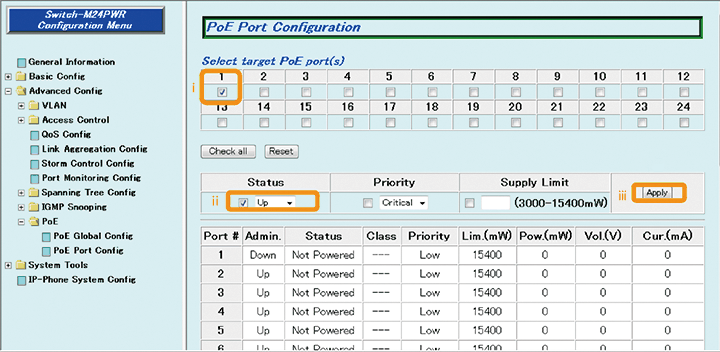
Step 4. Turn on the PoE power supply function of Port 1.
1) Place a check in “1” for Select target PoE port(s) (i).
2) Select “Up” for Status and place a check (ii).
3) Apply the change by “Apply” (iii).
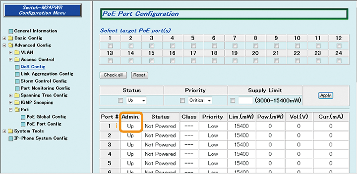
Step 5. Confirm that the PoE power supply function of Port 1 has been turned on (Up).
1) Confirm that Admin of Port 1 is “Up” (i).
* The power supply of the PoE-compliant terminal connected to Port 1 is turned on.
ここからサブメニューです。