ページの先頭です。
ここから本文です。
Ethernet Switch Link Aggregation Setting Procedure (for WEB)
Introduction
This setting example explains the procedure of Ethernet Switch Link Aggregation setting for switches.
Applicable models
| Applicable models | |
|---|---|
| Product name | Product number |
| Switch-M24eGLPWR+ | PN28248 |
| Switch-M16eGLPWR+ | PN28168 |
| Switch-M12eGLPWR+ | PN28128 |
| Switch-M8eGLPWR+ | PN28088 |
| Switch-M5eGLPWR+ | PN28058 |
| Switch-M24PWR | PN23249K |
| Switch-M16PWR | PN23169K |
| Switch-M12PWR | PN23129K |
Overview
Set the switch so that the link aggregation is used for the route redundancy and to extend the communication bandwidth.

Setting Flow(Common to both Switch-M24PWR-1 and Switch-M24PWR-2)
- 1.Connect to Web management screen of Switch-M24PWR.
- 2.Set Switch-M24PWR.
- 1) Set the link aggregation ID.
- 2) Select the port to set the link aggregation. (In this setting, ports No. 25 and 26)
- 3) Set the link aggregation mode to active.
- 3.Connect between ports No. 25 and 26 of both switches respectively, and confirm the communication.
Setting Procedure
Step 1.
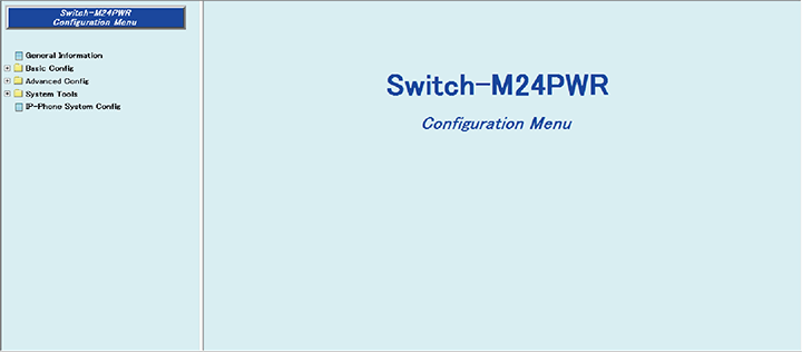
Connect to the Web management screen of Switch-M24PWR and login. Connect the PC and Ethernet Switch using a twisted pair cable and console cable, and connect to the Web management screen of Switch-M24PWR.
(Refer to setting example "Connection Procedures to Ethernet Switch Web Management Screen" for the procedure to connect to the Web management screen)

Step 2.Set the link aggregation.
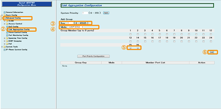
1) Select “Advanced Config” -> ”Link Aggregation Config” ((1) -> (2)).
2) Enter "1" in “Key” ((3)).
3) Change “Mode” to ”LACP Active” ((4)).
4) Place checks in 25 and 26 of “Group Member ” ((5)).
5) Select “Add” to set ((6)).

Step 3.Save the settings.
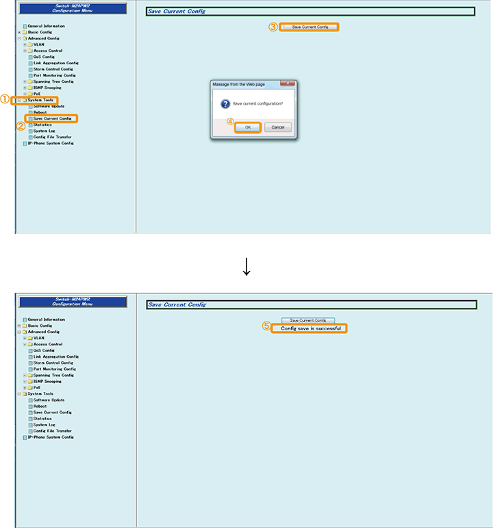
1) Select “System Tools” -> ”Save Current Config”. ((1) -> (2))
2) Save the settings by “Save Current Config” ((3))
3) Execute saving by “OK” ((4))
4) Confirm that the settings are saved successfully ((5))

Step 4.Connect the devices.
Connect the devices.
Step 5.Execute operation check.
Confirm that there is no loop occurring, and communication is possible between both switches.
Connect the device and check the communication.
ここからサブメニューです。