ページの先頭です。
ここから本文です。
Ethernet Switch VLAN Setting Procedure (for WEB)
Introduction
This setting example explains the procedure of Ethernet Switch VLAN setting for switches.
Applicable models
| Applicable models | |
|---|---|
| Product name | Product number |
| Switch-M24eGLPWR+ | PN28248 |
| Switch-M16eGLPWR+ | PN28168 |
| Switch-M12eGLPWR+ | PN28128 |
| Switch-M8eGLPWR+ | PN28088 |
| Switch-M5eGLPWR+ | PN28058 |
| Switch-M24PWR | PN23249K |
| Switch-M16PWR | PN23169K |
| Switch-M12PWR | PN23129K |
Overview
Allocate Port1-12 and Port13-25 to separate VLAN groups, set them to go through the uplink and enable them to communicate with only within their own group.
Set Port1-25 as ports for PC connection. Set Port26 as the uplink port.

Setting Flow(Common to both Switch-M24PWR-1 and Switch-M24PWR-2)
- 1.Connect to Web management screen of Switch-M24PWR.
- 2.Make the Switch-M24PWR-1 VLAN setting.
- 1) Create 2 VLANs. (Set the VLAN ID, VLAN Name, and Port Members.)
- 2) Set the PVID and configure the Untag VLAN.
- 3) Save the settings.
- 3.Connect Switch-M24PWR-1 and Switch-M24PWR-2 and confirm that communication among the same VLAN is possible.
Setting Procedure
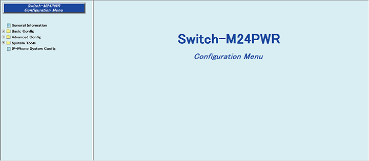
Step 1.Connect to the Web management screen of Switch-M24PWR and login.
Connect the PC and Ethernet Switch using a twisted pair cable (connect to the port No. 26) and console cable, and connect to the Web management screen of Switch-M24PWR.
(Refer to setting example "Connection Procedures to Ethernet Switch Web Management Screen" for the procedure to connect to the Web management screen)
Step 2.Create VLAN10.
1) Select “Advanced Config” -> ”VLAN” -> ”VLAN Creation”((1) -> (2) -> (3)).
2) Enter ”10” in “VLAN ID” ((4)).
3) Enter ”Group10” in “VLAN Name”((5)).
4) Click ”1 to12,26” in “Member Ports” ((6)).
5) Select “Apply” to apply the changes ((7)).

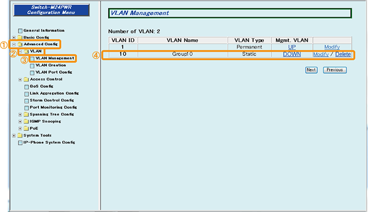
Step 3.Confirm that VLAN10 is created.
1) Select “Advanced Config” -> ”VLAN” -> ”VLAN Management” ((1) -> (2) -> (3))
2) Confirm that ”10” is added in “VLAN ID” ((4)).
Step 4.Create VLAN20.
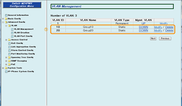
1) By similar procedures, set ”20” for ”VLAN ID”, ”Group20” for ”VLAN Name”, and ”13 to 26” for ”Member Ports”.
2) Confirm that VLAN20 is created. ((1))
Step 5.Set Untag VLAN for ports No. 1 to 12.
1) Select “Advanced Config” -> ”VLAN” -> ”VLAN Port Config” ((1) -> (2) -> (3)).
2) Place a check in ”1 to 12” of “Select target port(s)”((4)).
3) Enter ”10” in “PVID”, and place a check ((5)).
4) Select “Apply” to apply changes ((6)).
5) Confirm that the settings are changed ((7)).

Step 6.Set Untag VLAN for ports No. 13 to 25.
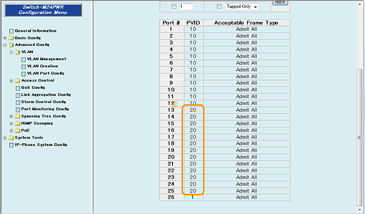
1) By similar procedures, place a check in ”13 to 25” of “Select target port(s)”, enter ”20” in “PVID” and place a check, and select ”Apply” to apply the changes.
2) Check that the settings are changed. ((1))
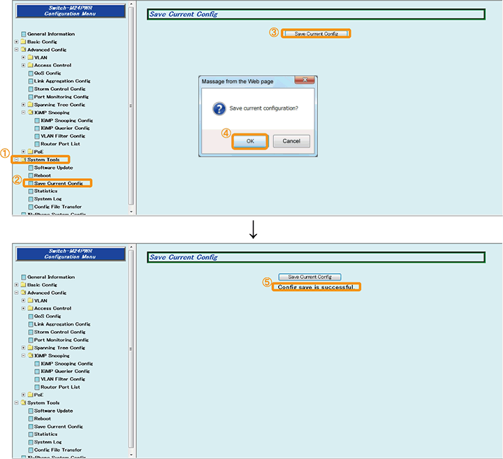
Step 7.Save the settings.
1) Select “System Tools”. -> ”Save Current Config”((1) -> (2)).
2) Save the settings by “Save Current Config”((3)).
3) Execute saving by “OK”((4)).
4) Confirm that the settings are saved successfully ((5)).
Step 8.Connect the devices.
Referring to the configuration example, connect the devices.
Step 9.Execute operation check.
Check that communication is possible between terminals within the same VLAN, and impossible between different VLANs.
Now the settings are complete. Connect the device and check the communication.
ここからサブメニューです。