ページの先頭です。
ここから本文です。
IP Address Setting Procedure (ZEQUO Series)
Introduction
This setting example explains the procedure of the IP Address setting for ZEQUO series switches.
Applicable models
| Applicable models | |
|---|---|
| Product name | Product number |
| ZEQUO 6400 | PN36240E |
| ZEQUO 2200 | PN26241 |
| ZEQUO 2210 | PN26161 |
Overview
Create 3 VLAN groups in ZEQUO 6400 and set the IP address for each group.
All ports belonging to each VLAN are transmitted and received by Untag.
Configuration Example

Setting content and procedure
- Delete all ports which are set as the default from the port members of VLAN group 1 (VID=1 VLAN NAME=default).
- Allocate Port1-8 to VLAN group10 (VID=10, VLAN NAME=Group10), IP: 192.168.10.254/24.
- Allocate Port9-16 to VLAN group 20 (VID=20, VLAN NAME=Group20), IP: 192.168.20.254/24.
- Allocate Port17-24 to VLAN group 30 (VID=30, VLAN NAME=Group30), IP: 192.168.30.254/24.
- Port1-24 performs transmission and receiving by Untag.
Overall setting flow
- 1. Set VLAN for ZEQUO 6400-1.
- 1) By "config vlan command", delete all ports from VLAN group 1 port members.
- 2) By "create vlan command", set VID and VLAN Name.
- 3) By "config vlan command", set port members to the created VLAN.
- 4) By "config port_vlan command", set PVID for Port1-24.
- 5) Save the settings.
- 2. Set IP Address for ZEQUO 6400-1.
- 1) By "create ipif command", set the IP address for the VLAN created in (1).
- 2) Save the settings.
- 3. In ZEQUO 6400-1, confirm that communication is possible within the same VLAN and between VLANs.
Setting examples
Step 1.
Connect the PC and Ethernet Switch using a twisted pair cable and console cable, and display the setting screen on a terminal emulator such as ZEQUO assist Plus.
(Refer to Setting Example "Ethernet Switch Connection Procedure to a Console Port" for the procedure to display the setting screen on the console port)
Step 2.
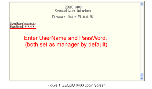
On the login screen, enter UserName and PassWord (both set as "manager" by default), and login to the setting screen. (Refer to Figure 1)

Step 3.
Delete all ports which are set as the default from port members of VLAN Name: default and VID: 1.
After Z6400:admin#, enter command as shown in the following.
Z6400:admin#config vlan default delete 1-28
If the command is entered correctly, the following will be displayed.
Command: config vlan default delete 1-28
Success.
Step 4.
Create a VLAN with VLAN Name: Group 10 and VID: 10.
Z6400:admin#create vlan Group10 tag 10
Command: create vlan Group10 tag 10
Success.
Step 5.
Add port members to the VLAN created in Step 4.
Z6400:admin#config vlan Group10 add untagged 1-8
Command: config vlan Group10 add untagged 1-8
Success.
Step 6.
Allocate PVID: 10 to port1-8, the port members created in Step 5.
Z6400:admin#config port_vlan 1-8 pvid 10
Command: config port_vlan 1-8 pvid 10
Success.
Step 7.
Similarly, set VLAN Group20 to port9-16.
Z6400:admin#create vlan Group20 tag 20
Command: create vlan Group20 tag 20
Success.
Z6400:admin#config vlan Group20 add untagged 9-16
Command: config vlan Group20 add untagged 9-16
Success.
Z6400:admin#config port_vlan 9-16 pvid 20
Command: config port_vlan 9-16 pvid 20
Success.
Step 8.
Similarly, set VLAN Group30 to port17-24.
Z6400:admin#create vlan Group30 tag 30
Command: create vlan Group30 tag 30
Success.
Z6400:admin#config vlan Group30 add untagged 17-24
Command: config vlan Group30 add untagged 17-24
Success.
Z6400:admin#config port_vlan 17-24 pvid 30
Command: config port_vlan 17-24 pvid 30
Success.
Step 9.
When settings for each VLAN are complete, save the settings.
Z6400:admin#save
Command: save
Success.
Step 10.
Set the IP address to VLAN: Group10. An arbitrary interface name can be set (here, IP10 is set as an example).
Z6400:admin#create ipif IP10 192.168.10.254/24 Group10 state enable
Command: create ipif IP10 192.168.10.254/24 Group10 state enable
Success.
Step 11.
Similarly, set the IP addresses for VLAN: Group20 and Group30.
Z6400:admin#create ipif IP20 192.168.20.254/24 Group20 state enable
Command: create ipif IP20 192.168.20.254/24 Group20 state enable
Success.
Z6400:admin#create ipif IP30 192.168.30.254/24 Group30 state enable
Command: create ipif IP30 192.168.30.254/24 Group30 state enable
Success.
Step 12.
When all the settings are complete, save the settings.
Z6400:admin#save
Command: save
Saving all configurations to NV-RAM.......... Done.
Step 13.
When settings are complete, connect the terminals referring to the configuration example and perform communication test.
- Confirm that communication is possible between terminals within the same segment.
- Confirm that even between different segments, the communication is possible by routing.
ここからサブメニューです。