ページの先頭です。
ここから本文です。
Ethernet Switch BPDU Guard Setting Procedure
Introduction
This section explains the procedure of the Ethernet Switch BPDU Guard setting.
Applicable models
| Applicable models | |
|---|---|
| Product name | Product number |
| Switch-M24PWR | PN23249K |
| Switch-M16PWR | PN23169K |
| Switch-M12PWR | PN23129K |
Overview
When a spanning tree is enabled, BPDU packets are sent to shut down the port during a loop connection to prevent a broadcast storm occurrence.

Overall setting flow
- 1. Enable the Ethernet Switch spanning tree function.
- 2. Enable the Ethernet Switch BPDU Guard function.
- 3. Enable the function (BPDU Guard recovery function) that automatically recovers the port that was shut down by the BPDU Guard function.
Setting Procedure
Step 1.
Use a twisted pair cable and a console cable to connect the PC and Ethernet Switch, and display the setting screen on the Hyper Terminal.
(For the setting screen display method on the console port, refer to the setting example “Method for Connecting to the Ethernet Switch Console Port.”)
Step 2.
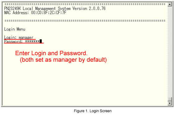
On the login screen, enter in Login and Password (both are manager in the initial state) to log into the setting screen.
(See Fig.1.)
Step 3.
From the Main Menu, select Advanced Switch Configuration. (See Fig.2.)

Step 4.
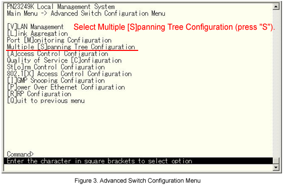
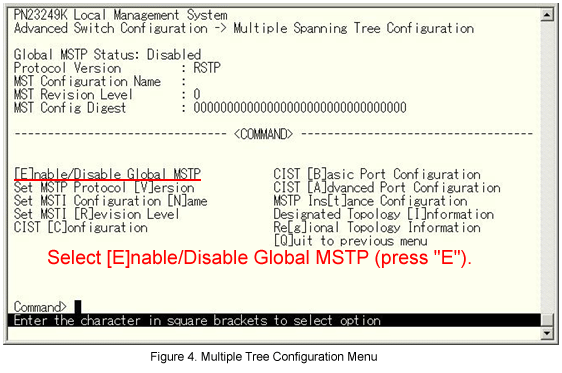
From the Advanced Switch Configuration Menu, select Multiple Spanning Tree Configuration. (See Fig.3.)
Step 5.
From the Advanced Switch Configuration Menu, select Multiple Spanning Tree Configuration. (See Fig.3.)
Step 6.
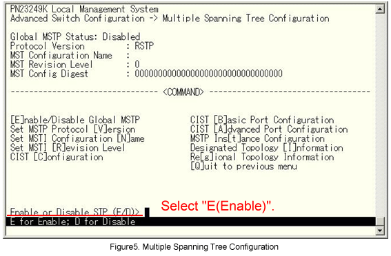
The message shown in Fig.5 is displayed. Enter E (Enable). (See Fig.5.)
Step 7.
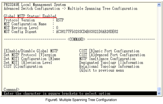
Global MSTP Status is changed from Disable to Enabled. (See Fig.6.)
Step 8.
From the Multiple Spanning Tree Configuration Menu, select CIST Basic Port Configuration. (See Fig.7.)

Step 9.
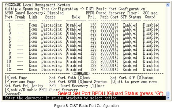
From the CIST Basic Port Configuration, select Set Port BPDU Guard Status. (See Fig.8.)
Step 10.
The message shown in Fig.9 is displayed. Select 0 (all ports). (See Fig.9.)

Step 11.
The message shown in Fig.10 is displayed. Enter E (Enabled).

Step 12.
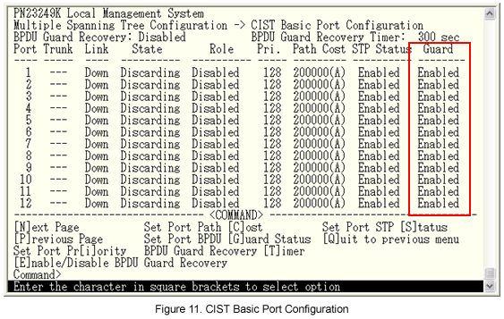
The Guard is changed from Disabled to Enabled. (See Fig.11.)
Step 13.
From the CIST Basic Port Configuration, select Enable/Disable BPDU Guard Recovery. (See Fig.12.)

Step 14.
The message shown in Fig.13 is displayed. Select E(Enable).

Step 15.
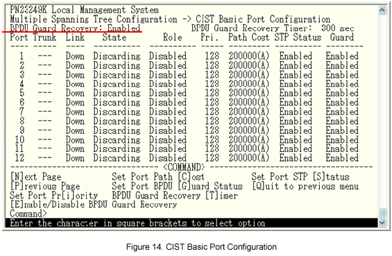
BPDU Guard Recovery is changed from Disabled to Enabled.
Step 16.
From the Main Menu, select Save Configuration to Flash. (See Fig.15.)

Step 17.
The message shown in Fig.16 is displayed. Select Y(Yes) to save the setting.

The setting is now completed.
ここからサブメニューです。