ページの先頭です。
ここから本文です。
Connection Procedures to Ethernet Switch Web Management Screen
Introduction
This setting example explains the procedure to set an IP address for the Ethernet Switch and connection procedures to Ethernet Switch Web Management Screen. For details on the settings and operation commands, refer to the user manuals on our website or other related instructions.
Applicable models (Models with web management function)
| With RJ45-DSub9 pin console cable (PN72002) | |
|---|---|
| Product name | Product number |
| Switch-M24PWR | PN23249K |
| Switch-M16PWR | PN23169K |
| Switch-M12PWR | PN23129K |
| Switch-M8ePWR | PN27089K |
Setting content and procedure
Set an IP address of the Ethernet Switch to enable access to the web management screen along with the following steps.

Overall setting flow
- 1. Set an IP address for the Ethernet Switch.
- 2. Enable the web management screen for the Ethernet Switch.
- 3. Save the settings of the Ethernet Switch.
- 4. Set an IP address for the PC and start the web browser.
- 5. Enter the IP address set for the Ethernet Switch in the address field of the web browser to log in.
Setting Procedure
Step 1.
Connect the PC and Ethernet Switch using a twisted pair cable and console cable, and display the setting screen on Hyper terminal.
(Refer to Setting Example "Ethernet Switch Connection Procedure to a Console Port" for the procedure to display the setting screen on the console port)
Step 2.
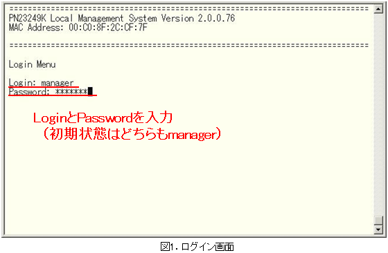
"On the login screen, enter Login and Password (both set as manager by default), and login to the setting screen. (Refer to Figure 1)
Step 3.
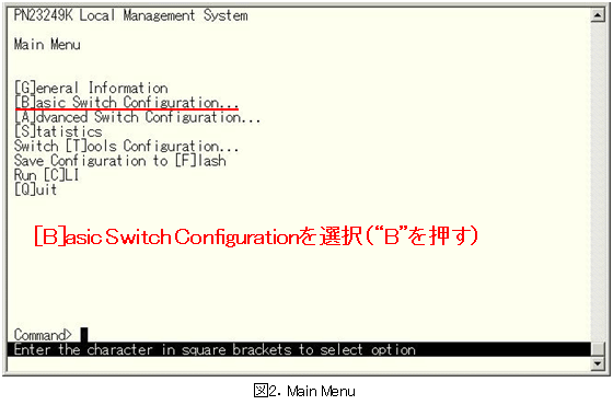
In Main Menu, select [B]asic Switch Configuration. (Refer to Figure 2)
Step 4.
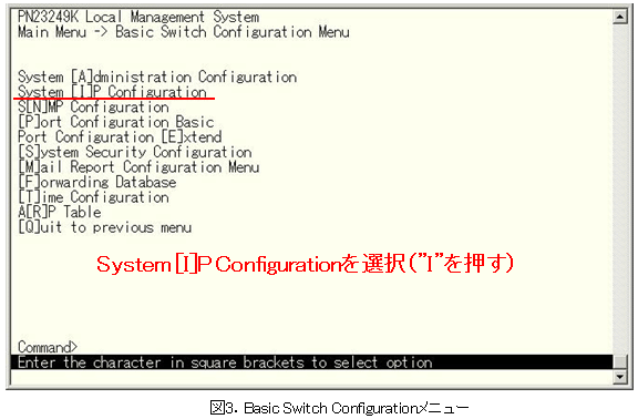
In Basic Switch Configuration Menu, select System [I]P Configuration. (Refer to Figure 3)
Step 5.
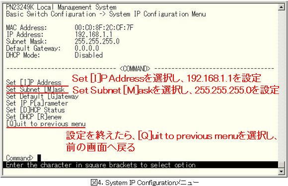
In System IP Configuration Menu, set an IP address. (Refer to Figure 4)
(e.g. IP address: 192.168.1.1 subnet mask: 255.255.255.0)
Step 6.
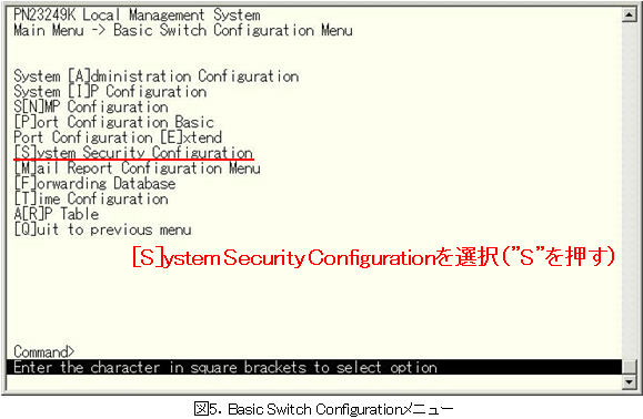
In Basic Switch Configuration Menu, select [S]ystem Security Configuration. (Refer to Figure 5)
Step 7.
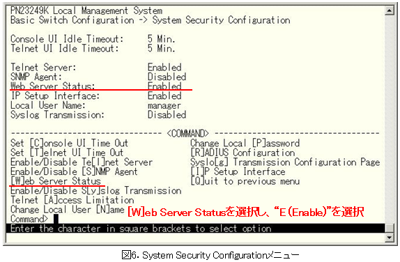
In System Security Configuration Menu, enable the Web Server Status. (Refer to Figure 6)
Step 8.
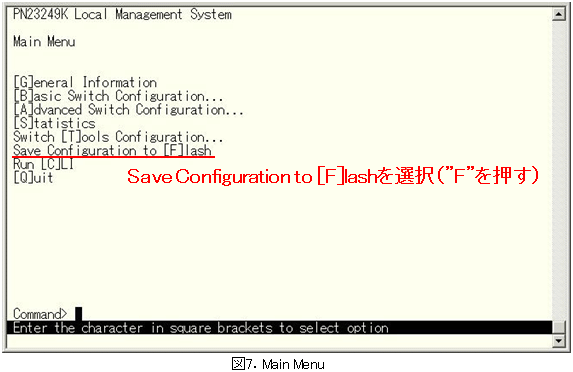
Go back to Main Menu and select Save Configuration to [F]lash. (Refer to Figure 7)
Step 9.
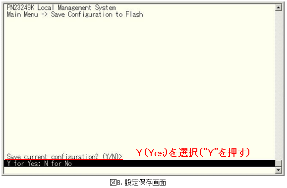
The screen shown in Figure 8 will be displayed. Select Y (Yes) to save the settings.
Step 10.
Start a web browser (such as Internet Explorer) on the PC, enter "192.168.1.1" in the address bar and click the [Go] button.
Step 11.
Enter User name and Password (both set as manager by default), and login to the setting screen. (Refer to Figure 9)
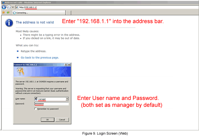
* For operations after login, refer to the user manual (web version) on our website or other related instructions.
ここからサブメニューです。