 Panasonic Electric Works Networks Co., Ltd. > Support > Setting Examples > VLAN Setting Procedure(GA-MU/XG-MU Series)(for WEB)
ここから本文です。
VLAN Setting Procedure(GA-MU/XG-MU Series)(for WEB)
Introduction
In this setting example, we will explain the VLAN settings for the GA-MU/XG-MU series.
Applicable models
Overview
VLAN is a function that allows virtual grouping within a network.
Configuration Example
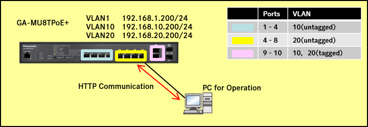
Explanation
The GA-MU8TPoE+ is divided into two networks: VLAN 10 and VLAN 20.
- Ports 1-8 are set as untagged (access ports), and ports 9-10 are set as tagged (trunk ports).
- Communication is allowed within VLAN 10 and within VLAN 20, but communication between VLAN 10 and VLAN 20 is not allowed.
Setting Procedure
Step 1.
Connect the PC to the LAN port of the switching hub.
Step 2.
On the login screen, enter the User Name and Password to log in to the Web interface.
Step 3.
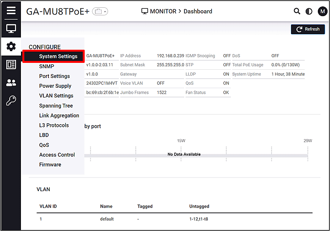
Follow the steps below to proceed to IP Settings.
CONFIGURE > System Settings > IP Settings
Step 4.
Change the IP Address. (IP:192.168.1.200 Subnet Mask:255.255.255.0)
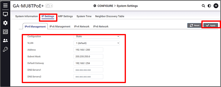
Step 5.
Create a VLAN.
CONFIGURE > VLAN settings > 802.1Q
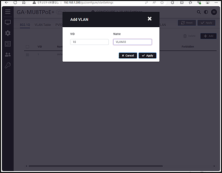
Click Add.
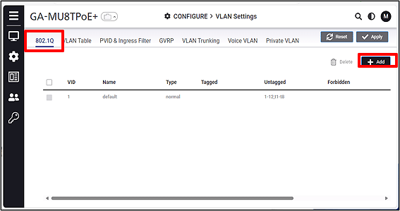
Enter the VID and VLAN Name.
(VID:10 Name:VLAN10 VID:20 Name:20)
Step 6.
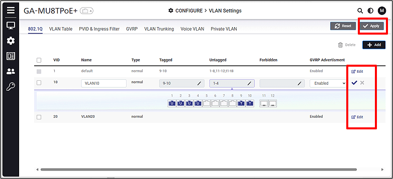
Click Edit, configure the VLAN members, and then click Apply.
(VLAN10 Untagged:1-4 Tagged:9-10 VLAN20 Untagged:5-8 Tagged:9-10)
Step 7.
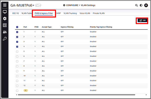
Set the PVID.
VLAN Settings > PVID & Ingress Filter
Select the port and click Edit.
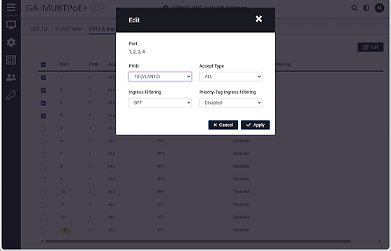
Set the PVID.
(Ports:1-4 PVID:10 Ports:5-8 PVID:20 Ports:9-10 PVID:1)
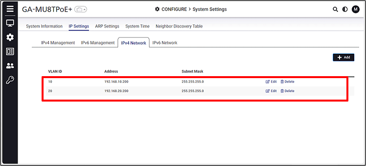
Step 8.
Set the IP address for the VLAN.
CONFIGURE > System Settings > IP Settings > IPv4 NetWork
(VLAN10:192.168.10.200/24 VLAN20:192.168.20.200/24)
ここからサブメニューです。