ページの先頭です。
ここから本文です。
ACL Setting Procedure
Introduction
This setting example explains the procedure of the ACL setting for switches.
Overview
On your switch, set VLANs and IP addresses.
Set ACL to control communication between VLANs.
* Communication (Ping, Telnet, etc.) to Ethernet Switches (in the following sample configuration, 192.168.10.254, 192.168.20.254, and 192.168.30.254) cannot be filtered if ACL is configured.
Configuration Example

Overall setting flow
- 1. Set Ports 1-8 to VLAN group 10 (VID=10 VLAN NAME=Group10), IP:192.168.10.254/24.
- 2. Set Ports 9-16 to VLAN group 20 (VID=20 VLAN NAME=Group20), IP:192.168.20.254/24.
- 3. Set Ports 17-24 to VLAN group 30 (VID=30 VLAN NAME=Group30), IP:192.168.30.254/24.
- 4. Set ACL to control communication between VLAN group 10 and VLAN group 20 so that they cannot communicate each other.
Setting Procedure
Step 1.
Connect the PC and Ethernet Switch using a twisted pair cable and console cable, and display the setting screen on Hyper terminal.
(Refer to Setting Example "Ethernet Switch Connection Procedure to a Console Port" for the procedure to display the setting screen on the console port)
Step 2.
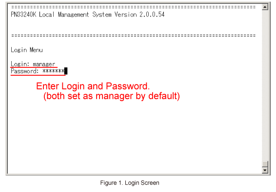
On the login screen, enter Login and Password (both set as manager by default), and login to the setting screen. (Refer to Figure 1)
Step 3.
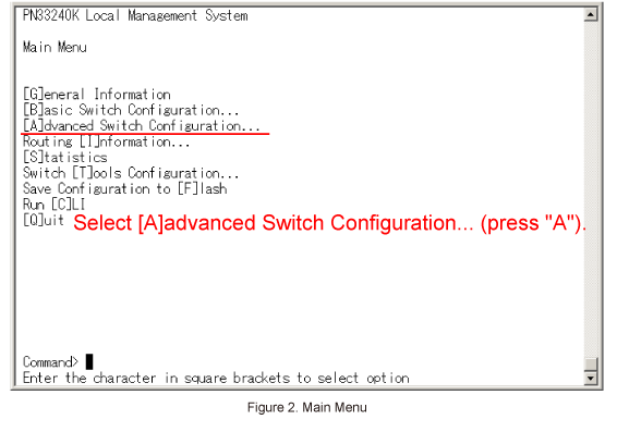
In Main Menu, select [A]dvanced Switch Configuration. (Refer to Figure 2)
Step 4.
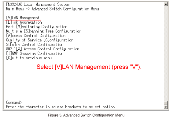
In Advanced Switch Configuration Menu, select [V]LAN Management. (Refer to Figure 3)
Step 5.
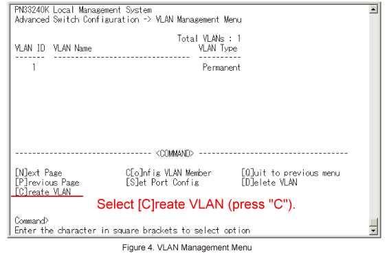
In VLAN Management Menu, select [C]reate VLAN. (Refer to Figure 4)
Step 6.
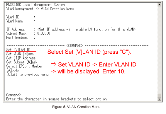
In VLAN Creation Menu, select Set [V]LAN ID. (Refer to Figure 5)
Step 7.
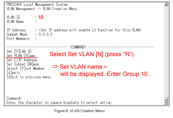
Then, in VLAN Creation Menu, select Set VLAN [N]ame. (Refer to Figure 6)
When Enter VLAN name > is displayed, enter Group10.
Step 8.
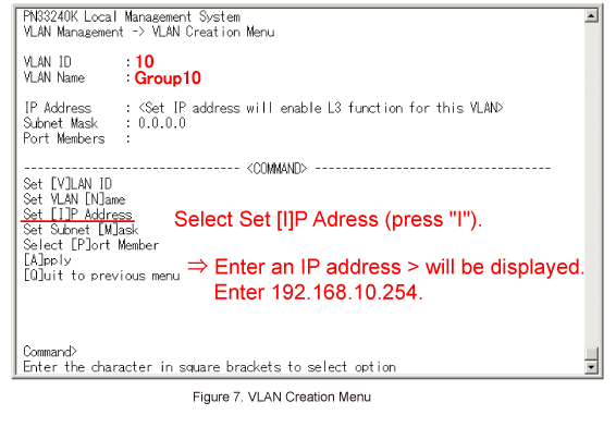
Then, in VLAN Creation Menu, select Set [I]P Address. (Refer to Figure 7)
When Enter an IP address > is displayed, enter 192.168.10.254.
Step 9.
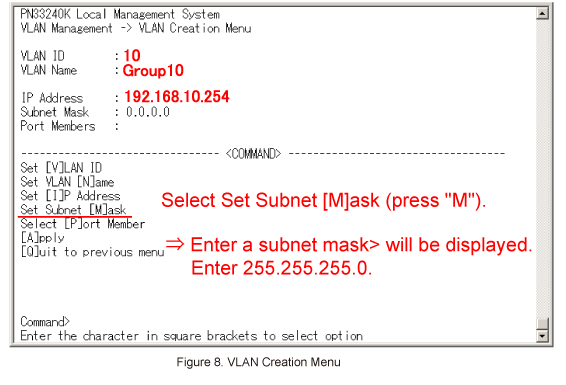
Then, in VLAN Creation Menu, select Set Subnet [M]ask. (Refer to Figure 8)
When Enter a subnet mask > is displayed, enter 255.255.255.0.
Step 10.
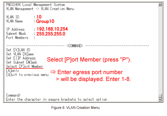
Then, in VLAN Creation Menu, select Select [P]ort Member. (Refer to Figure 9)
When Enter egress port number > is displayed, enter 1-8.
Step 11.
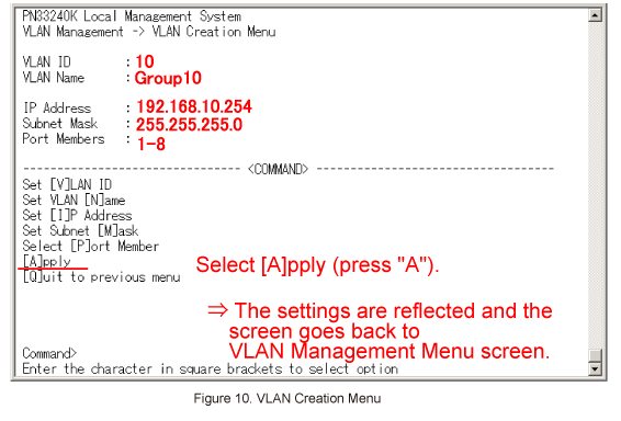
Once all of the items are entered in VLAN Creation Menu, select [A]pply. (Refer to Figure 10)
* If Quit to previous menu is selected without executing Apply, no setting will be applied and the display will go back to the previous screen.
Step 12.
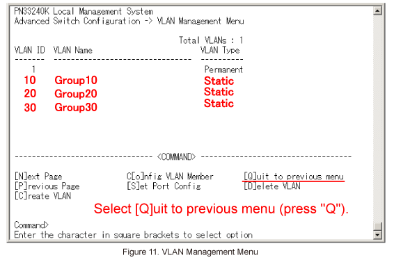
Follow Steps 5 to 11 to configure VLAN ID:20 and VLAN ID:30.
The following items must be specified.

Step 13.
Select [Q]uit to previous menu (press "Q") to go back to Advanced Switch Configuration Menu. (Refer to Figure 11)
Step 14.
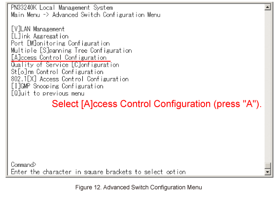
In Advanced Switch Configuration Menu, select Access Control Configuration. (Refer to Figure 12)
Step 15.
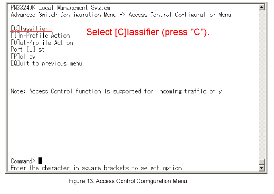
In Access Control Configuration Menu, select Classifier. (Refer to Figure 13)
Step 16.
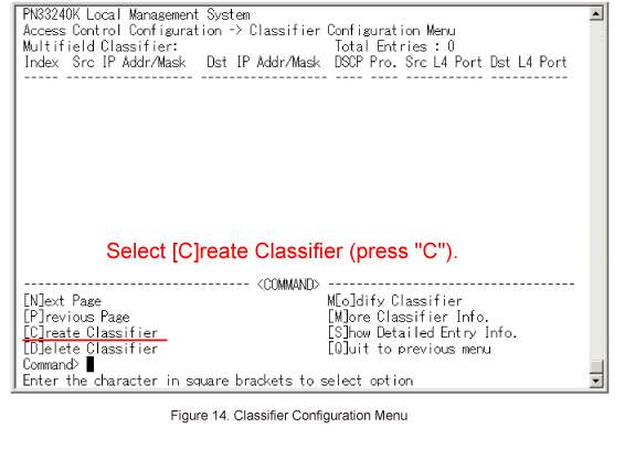
In Classifier Configuration Menu, select Create Classifier. (Refer to Figure 14)
Step 17.
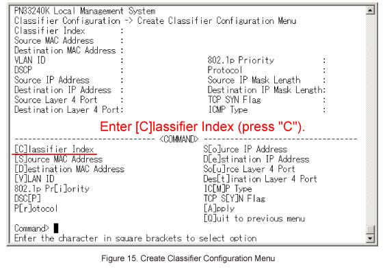
In Create Classifier Configuration Menu, select Classifier Index. (Refer to Figure 15)
When Enter Classifier Index > is displayed, enter 1.
Step 18.
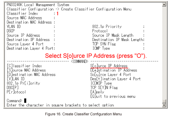
In Create Classifier Configuration Menu, select Source IP Address. (Refer to Figure 16)
When Enter source IP address > is displayed, enter 192.168.10.0.
Then, when Enter source IP address mask length > is displayed, enter 24.
Step 19.
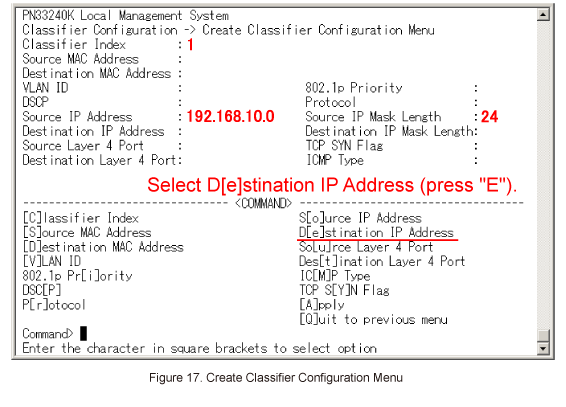
In Create Classifier Configuration Menu, select Destination IP Address. (Refer to Figure 17)
When Enter destination IP address > is displayed, enter 192.168.20.0.
Then, when Enter destination IP address mask length > is displayed, enter 24.
Step 20.
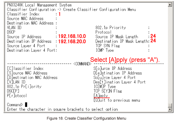
Once all of the necessary items are entered in Create Classifier Configuration Menu, select Apply. (Refer to Figure 18)
The settings are reflected, and the screen goes back to Classifier Configuration Menu.
Step 21.
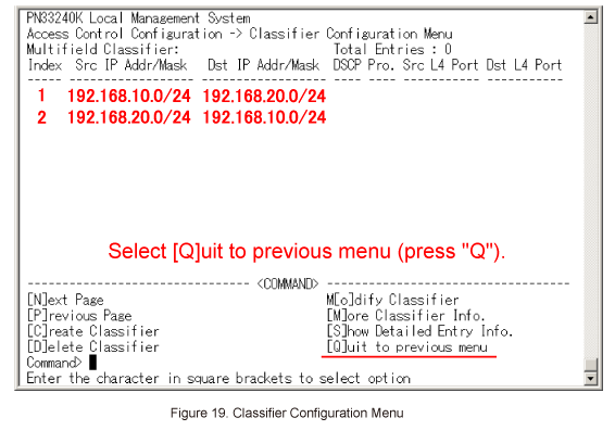
Similarly, enter 2 for Classifier Index and set the classifier for communication from 192.168.20.0 to 192.168.10.0.
The following items must be specified.

Step 22.
Select [Q]uit to previous menu (press "Q") to go back to Access Control Configuration Menu. (Refer to Figure 19)
Step 23.
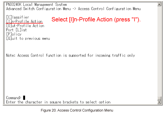
In Access Control Configuration Menu, select In-Profile Action. (Refer to Figure 20)
Step 24.
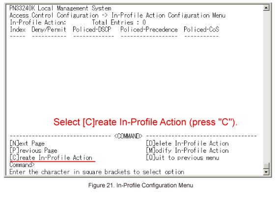
In In-Profile Action Configuration Menu, select Create In-Profile Action. (Refer to Figure 21)
Step 25.
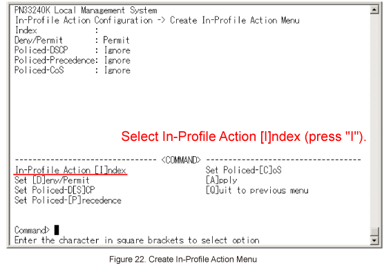
In Create In-Profile Action Menu, select In-Profile Action Index. (Refer to Figure 22)
When Enter in-profile action index > is displayed, enter 1.
Step 26.
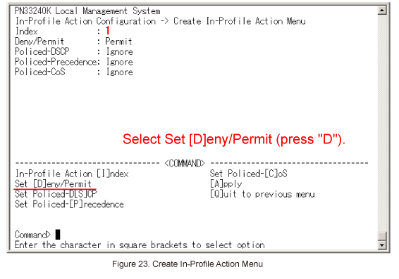
In Create In-Profile Action Menu, select Set [D]eny/Permit. (Refer to Figure 23)
When Select Deny/Permit (1-2) > is displayed, enter 1(Deny).
Step 27.
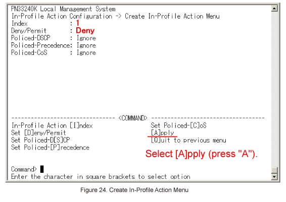
Once all of the necessary items are entered in Create In-Profile Action Menu, select [A]pply. (Refer to Figure 24)
Step 28.
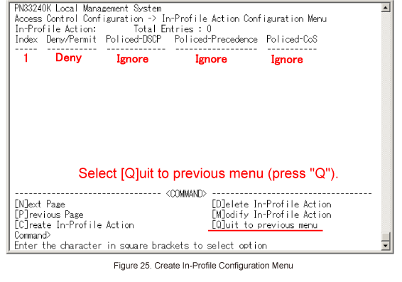
When In-Profile Action Configuration Menu is displayed again, select [Q]uit to previous menu to go back to Access Control Configuration Menu. (Refer to Figure 25)
Step 29.
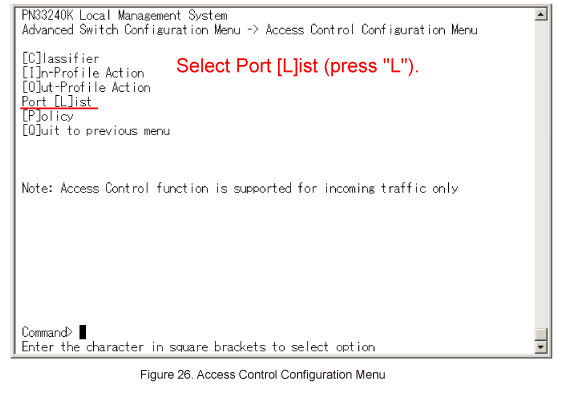
In Access Control Configuration Menu, select Port [L]ist. (Refer to Figure 26)
Step 30.
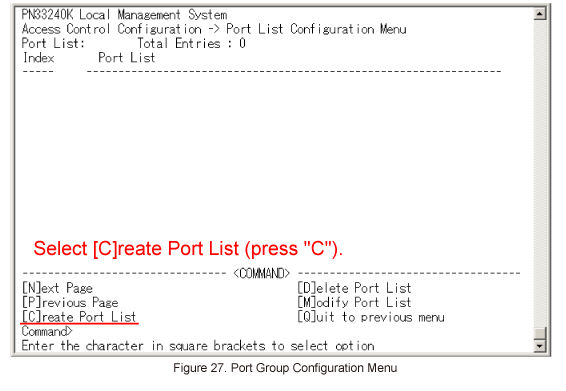
In Port List Configuration Menu, select [C]reate Port List. (Refer to Figure 27)
When Enter port list index > is displayed, enter 1.
Then, when Enter port list number e.g.: 1, 3, 5-26 > is displayed, enter 1-8.
Step 31.
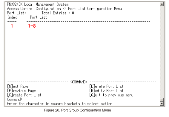
In Port List Configuration Menu, confirm the settings have been applied. (Refer to Figure 28)
Step 32.
Similarly, enter 2 for Port List Index and set Port List 9-16.
The following items must be specified.

Step 33.
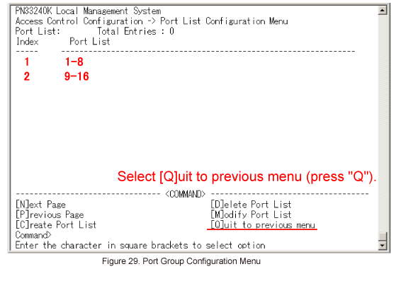
Once all of the items are entered in Port List Configuration Menu, select [Q]uit to previous menu. (Refer to Figure 29)
Access Control Configuration Menu will be displayed again.
Step 34.
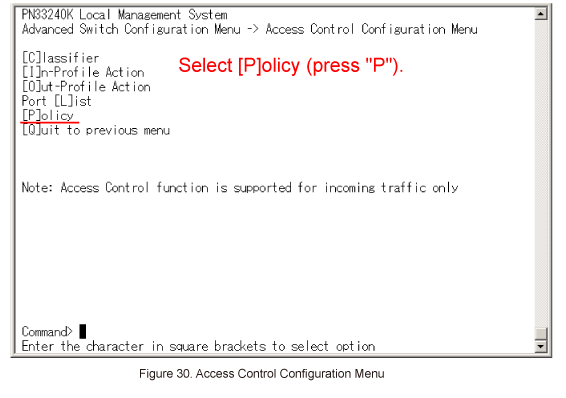
In Access Control Configuration Menu, select [P]olicy. (Refer to Figure 30)
Step 35.
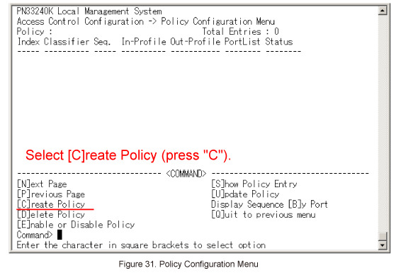
In Policy Configuration Menu, select [C]reate Policy. (Refer to Figure 31)
Step 36.
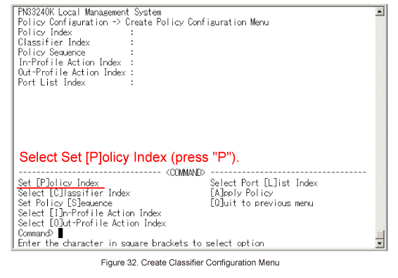
In Create Policy Configuration Menu, select Set [P]olicy Index. (Refer to Figure 32)
When Enter policy index > is displayed, enter 1.
Step 37.
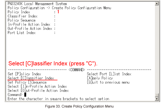
In Create Policy Configuration Menu, select Select [C]lassifier Index. (Refer to Figure 33)
When Enter classifier index > is displayed, select the index number of the classifier which was configured in Classifier Configuration.
Enter 1.
Step 38.
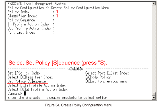
In Create Policy Configuration Menu, select Set Policy [S]equence. (Refer to Figure 34)
When Enter policy sequence > is displayed, enter a sequence number (any number).
Enter 1 in this case.
Step 39.
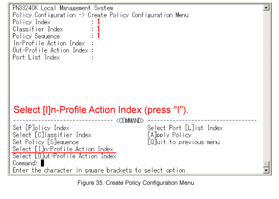
In Create Policy Configuration Menu, select Select [I]n-Profile Action Index. (Refer to Figure 35)
When Enter in-profile index > is displayed, select the index number of the In-Profile Action which was configured using In-Profile Action Configuration Menu.
Enter 1.
Step 40.
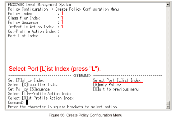
In Create Policy Configuration Menu, select Select Port [L]ist Index. (Refer to Figure 36)
When Enter port list index > is displayed, select the index number of the port list which was created in Port List Configuration Menu.
Enter 1.
Step 41.
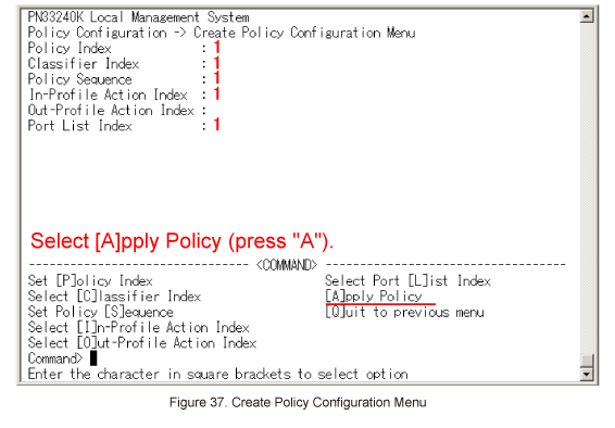
Once all of the items are entered in Create Policy Configuration Menu, select [A]pply Policy. (Refer to Figure 37)
Policy Configuration Menu will be displayed again.
Step 42.
Similarly, enter 2 for Policy Index and set a policy to control communication from 192.168.20.0 to 192.168.10.0.
The following items must be specified.

Step 43.
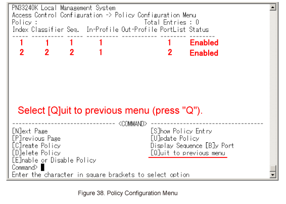
In Policy Configuration Menu, select [Q]uit to previous menu. (Refer to Figure 38)
Step 44.
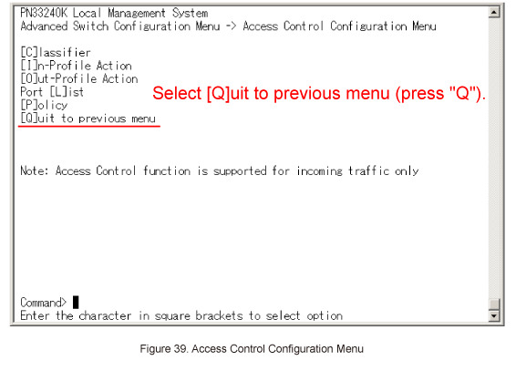
In Access Control Configuration Menu, select [Q]uit to previous menu. (Refer to Figure 39)
Step 45.
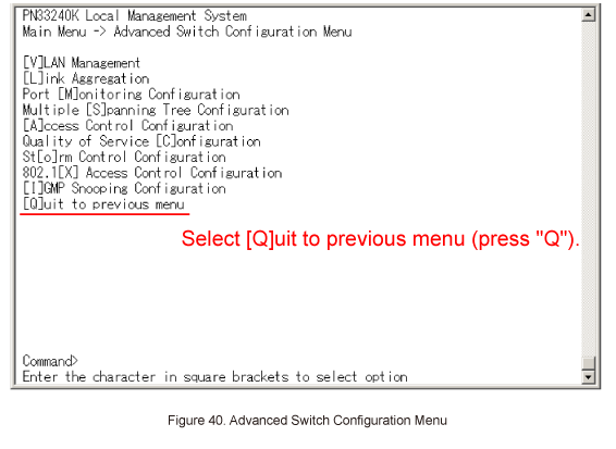
In Advanced Switch Configuration Menu, select [Q]uit to previous menu. (Refer to Figure 40)
Step 46.
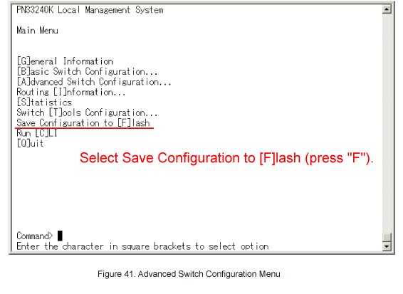
In Main Menu, select Save Configuration to [F]lash. (Refer to Figure 41)
Save current configuration?(Y/N) > will be displayed. Select "Y" to save the settings, or "N".
Step 47.
Check if communication is controlled successfully by access control.
ここからサブメニューです。