ページの先頭です。
![]() Panasonic Electric Works Networks Co., Ltd. > Support > Setting Examples > SNTP Setting Procedure
Panasonic Electric Works Networks Co., Ltd. > Support > Setting Examples > SNTP Setting Procedure
ここから本文です。
SNTP Setting Procedure
Introduction
This setting example explains SNTP time synchronization for switches. (In this setting example, manual time setting is not performed.)
Applicable models
Overview
Configure SNTP settings so that the switch can synchronize with an SNTP server to obtain the time information.
Configuration Example

Overall setting flow
SNTP Time Synchronization
- 1. Set Switch-M24PWR.
- 1) Set the IP address as 192.168.1.254/24.
- 2) Set the IP address of the SNTP server. Also, if necessary, specify other settings including the SNTP polling time and the time zone.
- 2. Connect Switch-M24PWR and the SNTP server as shown in the configuration diagram.
- 3. Confirm that Switch-M24PWR can synchronize with the SNTP server to obtain the time information.
Setting Procedure
Step 1.
Connect the PC and Ethernet Switch using a twisted pair cable and console cable, and display the setting screen on Hyper terminal.
(Refer to Setting Example "Ethernet Switch Connection Procedure to a Console Port" for the procedure to display the setting screen on the console port)
Step 2.
On the login screen, enter Login and Password (both set as manager by default), and login to the setting screen. (Refer to Figure 1)

Step 3.
In Main Menu, select [B]asic Switch Configuration. (Refer to Figure 2)

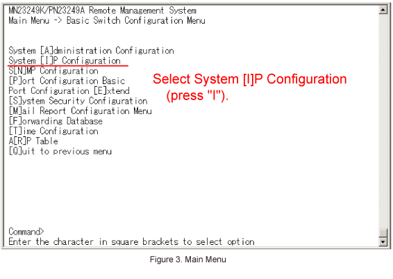
Step 4.
In Basic Switch Configuration Menu, select System [I]P Configuration. (Refer to Figure 3)
Step 5.
In System IP Configuration Menu, select Set [I]P Address and enter the IP address (192.168.1.254). (Refer to Figure 4)

Step 6.
In System IP Configuration Menu, select Set Subnet [M]ask and enter the subnet mask (255.255.255.0).
Step 7.
After performing all the settings, confirm that the settings are in the following status. (Refer to Figure 5)

Step 8.
In System IP Configuration Menu, select [Q]uit to previous menu to go back to Basic Switch Configuration Menu.
Step 9.
In Basic Switch Configuration Menu, select [T]ime Configuration. (Refer to Figure 6)

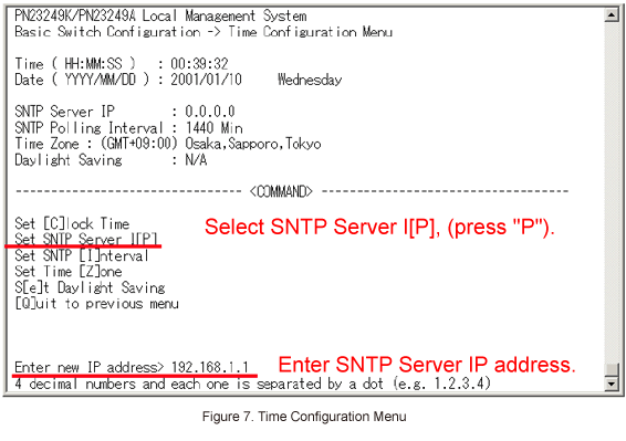
Step 10.
In Time Configuration Menu, select Set SNTP Server I[P] and enter the IP address of the SNTP server. (Refer to Figure 7)
Step 11.
When the IP address of the SNTP has been applied, display of Time Configuration Menu will be changed as shown in Figure 8.

Step 12.
Referring to the configuration diagram, connect Switch-M24PWR and the SNTP server.
Confirm that the time of Switch-M24PWR is synchronized with that of the SNTP server in the way that the time of the SNTP server is reflected on Switch-M24PWR.
* By default, the time synchronization interval is set to 1,440 minutes.
If you want to apply the time immediately, select Set SNTP [I]nterval and enter 1 to Interval Time.
Then, SNTP Polling Interval is displayed as 1 Min and the time is synchronized within one minute.
Once the time is synchronized, change SNTP Polling Interval to a desired value.

Step 13.
When all of the settings are complete, go back to the Main Menu using [Q]uit to previous menu, and from Main Menu select Save Configuration to [F]lash to save the settings. (Refer to Figure 10)
Save current configuration? (Y/N)> will be displayed. Enter "Y" to save the settings.

ここからサブメニューです。
![]() Panasonic Electric Works Networks Co., Ltd. > Support > Setting Examples > Syslog Transfer Setting Procedure
Panasonic Electric Works Networks Co., Ltd. > Support > Setting Examples > Syslog Transfer Setting Procedure
![]()